
LED guide rail lamp rotating structure

A technology of rotating structure and track light, which is applied to semiconductor devices of light-emitting elements, lighting and heating equipment, lighting devices, etc., can solve the problems of easy aging, inconvenient use, and inconvenient adjustment of the lighting angle of the lamp body during use, and achieve Improve the stability of rotation, easy installation of the lamp body, and good installation stability

Active Publication Date: 2018-08-07
深圳市肖恩德科技有限责任公司
View PDF5 Cites 2 Cited by
  • Summary
  • Abstract
  • Description
  • Claims
  • Application Information

AI Technical Summary

Problems solved by technology

[0002] In the prior art, the rotating structure of the LED track light is difficult to rotate, and it is easy to age during use, resulting in poor rotation stability; in the prior art, the rotating structure of the LED track light is inconvenient to adjust the illumination angle of the lamp body, and The installation and operation of the lamp body is cumbersome, the installation stability is not good, and the use is inconvenient, so a LED track light rotation structure is needed to solve the above problems

Method used


Image

  • LED guide rail lamp rotating structure
  • LED guide rail lamp rotating structure
  • LED guide rail lamp rotating structure

Examples


Embodiment Construction

[0018] In order to make the technical means, creative features, goals and effects achieved by the present invention easy to understand, the present invention will be further described below in conjunction with specific embodiments.

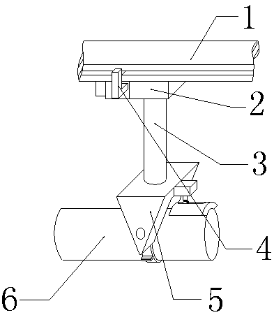
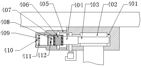
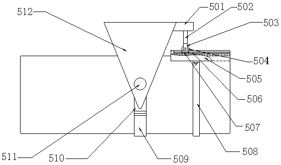
[0019] see Figure 1-Figure 3 , the present invention provides a technical solution: a rotating structure of LED track lights, including a track 1, a moving seat 2, a boom 3, a rotating assembly 4, an installation adjustment assembly 5 and a lamp body 6, and the moving seat 2 is assembled on the lower end of the track 1 , the upper end of the boom 3 is connected with the moving seat 2 through the rotating assembly 4, the installation adjustment assembly 5 is installed at the lower end of the suspension rod 3, the lamp body 6 is assembled inside the installation adjustment assembly 5, and the rotation assembly 4 includes a cavity 401, a turntable 402, a gear 1 403, gear 2 404, box body 405, installation tube 406, sponge sleeve 407, arc chamber 408,...


PUM


Abstract

The invention provides an LED guide rail lamp rotating structure comprising a track, a movement seat, a suspension rod, a rotating assembly, an installation adjustment assembly and a lamp body. The movement seat is assembled to the lower end of the track, the upper end of the suspension rod is connected with the movement seat through the rotating assembly, the installation adjustment assembly is installed at the lower end of the suspension rod, and the lamp body is assembled inside the installation adjustment assembly. The rotating assembly comprises a cavity, a rotary table, a first gear, a second gear, a box body, an installation barrel, a sponge sleeve, an arc chamber, an oil storage cavity, a first electric push rod, a push plate and a conveying pipe. The installation adjustment assembly comprises a fixing fixed station, a second electric push rod, a connection seat, a supporting seat, an arc plate, a cross-shaped sliding chute, a cross-shaped sliding block, a clamping ring, a lower connection ring, an upper connection ring, a fixing shaft and a connection frame. Compared with the prior art, the LED guide rail lamp rotating structure has the following beneficial effects that the purpose of improving the rotating steadiness is achieved, the purpose of adjusting the lamp body irradiation angle is also achieved, the lamp body is convenient to install, and installation stability is good.

Description

technical field [0001] The invention is a rotating structure of an LED guide rail lamp, which belongs to the field of lighting equipment. Background technique [0002] In the prior art, the rotating structure of the LED track light is difficult to rotate, and it is easy to age during use, resulting in poor rotation stability; in the prior art, the rotating structure of the LED track light is not convenient for adjusting the illumination angle of the lamp body, and The installation and operation of the lamp body is cumbersome, the installation stability is not good, and the use is inconvenient. Therefore, a rotating structure of the LED track lamp is needed to solve the above-mentioned problems. Contents of the invention [0003] In view of the deficiencies in the prior art, the purpose of the present invention is to provide a rotating structure of LED track lights to solve the problems raised in the above-mentioned background technology. [0004] In order to achieve the a...

Claims


Application Information

Patent Timeline
Patent Type & Authority Applications(China)
IPC IPC(8): F21S8/00F21V14/02F21V21/34F21V23/06F21Y115/10
CPCF21S8/00F21V14/02F21V21/34F21V23/06F21Y2115/10
Inventor 马永健
Owner 深圳市肖恩德科技有限责任公司
Learn More