
Method for selecting scanning area from multiple single areas based on pathological section scanning device

A technology of pathological slices and scanning devices, which is applied in the field of slice scanning, can solve the problems of increasing time for reading non-interest regions, increasing time for reading slices, wasting scanning resources, etc., and achieves the goal of improving transmission efficiency, reducing storage costs, and reducing scanning time Effect

Inactive Publication Date: 2018-08-07
杭州零跑路健康科技有限公司
View PDF4 Cites 4 Cited by
  • Summary
  • Abstract
  • Description
  • Claims
  • Application Information

AI Technical Summary

Problems solved by technology

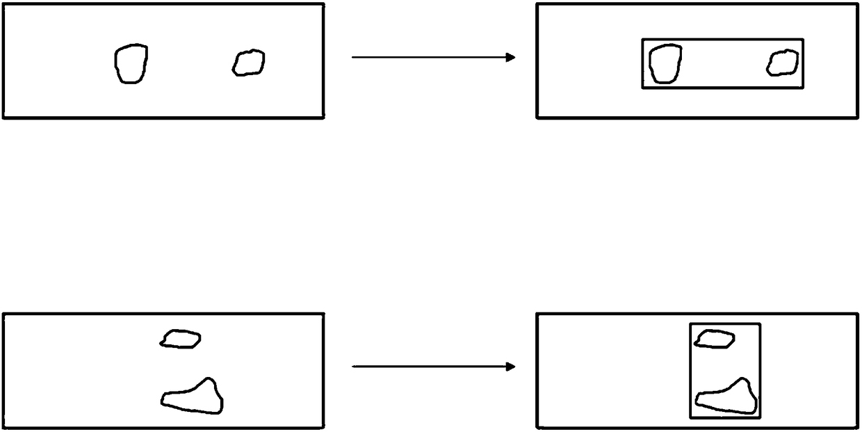
[0003] However, the existing pathological slice scanning devices all select a single area for scanning. For some special pathological slices, because the scanning objects are scattered on the slice, if a single area is selected, a large part of the scanning area will be a blank area, or It is a non-interest area, which leads to a waste of scanning time, increases the time to read the non-interest area, and reduces work efficiency
like figure 1 As shown in , there are two scanned objects far apart on each slide, using the existing scanning method, there will be figure 1 The scanning result on the right is a large blank area in the scanning area, which prolongs the scanning time, wastes scanning resources, and increases the time for reading slices
[0004] Therefore, there is an urgent need for a pathological slice scanning method that can freely select the scanning area, reduce the scanning time, and reduce the cost of digital image storage, but there is no report on this scanning method at present

Method used


Image

  • Method for selecting scanning area from multiple single areas based on pathological section scanning device
  • Method for selecting scanning area from multiple single areas based on pathological section scanning device
  • Method for selecting scanning area from multiple single areas based on pathological section scanning device

Examples


Embodiment Construction

[0028] The following will clearly and completely describe the technical solutions in the embodiments of the present invention with reference to the accompanying drawings in the embodiments of the present invention. Obviously, the described embodiments are only some, not all, embodiments of the present invention. Based on the embodiments of the present invention, all other embodiments obtained by persons of ordinary skill in the art without making creative efforts belong to the protection scope of the present invention.

[0029] It should be noted that, in the case of no conflict, the embodiments of the present invention and the features in the embodiments can be combined with each other.

[0030] The present invention will be further described below in conjunction with the accompanying drawings and specific embodiments, but not as a limitation of the present invention.

[0031] A preferred embodiment, such as figure 1 As shown, a method for selecting a scanning area based on ...


PUM


Abstract

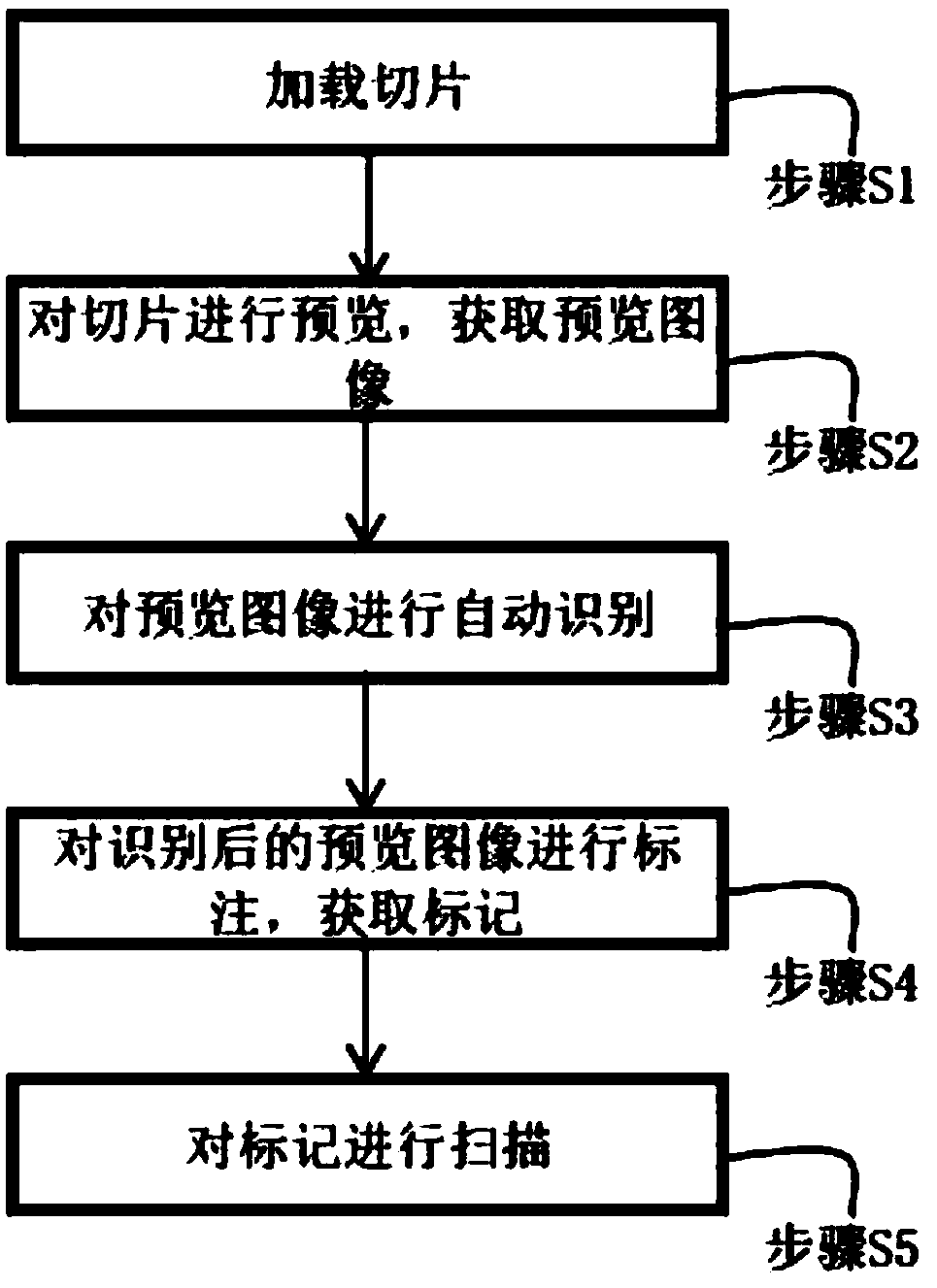
The invention relates to a method for selecting a scanning area from multiple single areas based on a pathological section scanning device. Recognition procedures are arranged in the pathological section scanning device. The method includes the steps: S1 loading a pathological section; S2 previewing the pathological section to obtain a previewing image; S3 automatically recognizing the previewingimage by the recognition procedures, and recognizing an organization area in the previewing image; S4 labeling the organization area through a preset labeling method to obtain corresponding markers; S5 scanning the markers to obtain a scanning result. The method has the advantages that the method is freer and more flexible, one or a plurality of scanning areas can be defined and selected, an actual needed scanning portion is only scanned, blank area scanning is decreased, uninterested area reading time is shortened, storage space is reduced, storage cost is reduced, the scanning areas are separately selected, and the whole scanning area is the sum of all the separately selected scanning areas.

Description

technical field [0001] The invention relates to the technical field of slice scanning, in particular to a method for selecting a scanning area based on multiple single areas of a pathological slice scanning device. Background technique [0002] A pathological slide is a type of pathological specimen. When making pathological slices, technicians treat some diseased tissues or organs through various chemicals and embedding methods to fix and harden the tissues or organs, cut them into thin slices on a microtome, and adhere them to glass slides. Staining is then carried out so that technicians can examine under a microscope to observe pathological changes and make corresponding pathological diagnoses to provide assistance for clinical diagnosis and treatment. The pathological slice scanning device is a tool for transforming pathological slices from physical to digital, thus replacing traditional microscopes. [0003] However, the existing pathological slice scanning devices a...

Claims


Application Information

Patent Timeline
Patent Type & Authority Applications(China)
IPC IPC(8): G01N21/84G01N21/01
CPCG01N21/01G01N21/84
Inventor 张仁洁方阳
Owner 杭州零跑路健康科技有限公司
Learn More