Chromatic confocal system

A technology of focal length and wavelength, applied in the direction of die cups, instruments, catheters, etc., can solve the problem of inaccurate measurement data, and achieve the effect of improving measurement accuracy

Active Publication Date: 2017-05-31
ALIGN TECH
View PDF4 Cites 0 Cited by
  • Summary
  • Abstract
  • Description
  • Claims
  • Application Information

AI Technical Summary

Problems solved by technology

The thickness of the coating should meet specific, difficult-to-control requirements, which leads to inaccurate measurement data

Method used


Image

  • Chromatic confocal system
  • Chromatic confocal system
  • Chromatic confocal system

Examples


Embodiment Construction

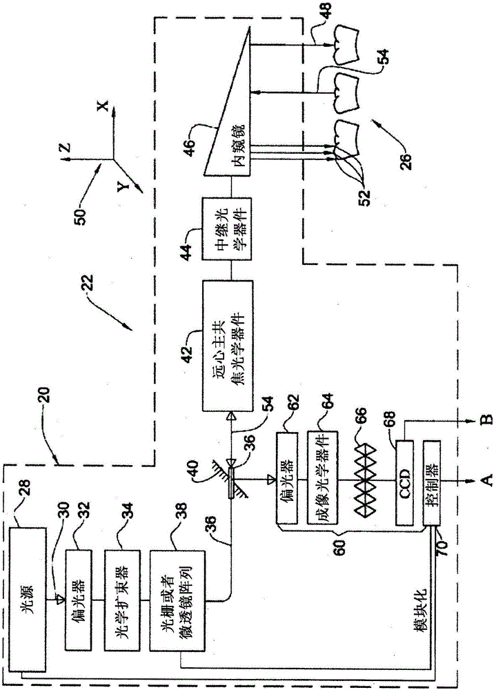
[0021] In various embodiments, the systems and methods described herein for determining the surface topography of a three-dimensional structure focus a two-dimensional array of light beams of multiple wavelengths to multiple focal lengths relative to the optical assembly. The surface topography can be determined by determining the wavelength with the best focus at each point in the two-dimensional field of view. Since each of the multiple wavelengths is focused to its unique focal length, the distance to each point can be inferred. The beam array can be used to simultaneously illuminate the structure being measured throughout the two-dimensional field of view. In various embodiments, the two-dimensional array of light beams projects the two-dimensional array of light spots onto the structure. Throughout the two-dimensional field of view, the light reflected from each spot on the structure can be directed to the two-dimensional detector, which is configured to process the refle...


PUM


Abstract

A system for determining surface topography of a three-dimensional structure is provided. The system can include an illumination unit configured to output a two-dimensional array of light beams each comprising a plurality of wavelengths. An optical assembly can focus the plurality of wavelengths of each light beam to a plurality of focal lengths so as to simultaneously illuminate the structure over a two-dimensional field of view. A detector and a processor are used to generate data representative of the surface topography of the three-dimensional structure based on the measured characteristics of the light reflected from the structure.

Description

Background technique [0001] Various methods have been developed for optical measurement of surface topography. For example, optical systems and methods that can be used to optically measure the surface topography of a patient's teeth have been developed and adopted. For example, the measured surface topography of the teeth can be used to design and manufacture dentures and / or determine orthodontic treatment plans to correct malocclusions. [0002] One technique for optically measuring surface topography uses laser triangulation to measure the distance between the surface of the tooth and the optical path probe inserted into the patient's mouth. However, the surface topography measured via laser triangulation may not be as accurate as desired due to, for example, suboptimal reflectivity from the tooth surface. [0003] Other technologies for optical measurement of surface topography implemented in the CEREC-1 and CEREC-2 systems commercially available from Siemens GmbH or Sirona De...

Claims


Application Information

Patent Timeline
Patent Type & Authority Applications(China)
IPC IPC(8): G01B11/25
CPCG01B2210/50A61B1/00009A61B1/04A61B1/06A61B1/0638A61B1/24A61B5/1076A61B5/1079A61B5/0088A61B5/4547G01B11/25A61B1/00194A61B1/0605A61C9/006G01B11/24A61C1/088A61C9/0066
Inventor 优素福·阿缇亚塔勒·维科尔
Owner ALIGN TECH
Why Eureka
Try Eureka