
A wireless charging device for automatic directional transmission

A directional transmission and wireless charging technology, applied in the direction of circuit devices, electrical components, etc., can solve problems such as difficult alignment of the receiving coil and the transmitting coil, decrease in power transmission efficiency, and inability to align the transmitting coil and the receiving coil, etc., to achieve improved Effects of wireless charging efficiency, reduction of dissipation rate, and improvement of utilization rate

Active Publication Date: 2020-06-02
NANJING UNIV OF INFORMATION SCI & TECH
View PDF2 Cites 0 Cited by
  • Summary
  • Abstract
  • Description
  • Claims
  • Application Information

AI Technical Summary

Problems solved by technology

[0003] However, there is a defect in the current electromagnetic induction wireless charging method. It is necessary to align the transmitting coil with the receiving coil to achieve an efficient wireless charging process. When the transmitting coil and the receiving coil are slightly deviated, it will cause power transmission efficiency. However, when the user is charging the charging device, it is difficult to align the receiving coil with the transmitting coil, and it takes a lot of time to place the device to be charged on the designated position of the wireless charging device, which not only brings A lot of inconvenience has come, and it is impossible to align the transmitting coil with the receiving coil, so that the charging efficiency cannot be improved

Method used


Image

  • A wireless charging device for automatic directional transmission
  • A wireless charging device for automatic directional transmission
  • A wireless charging device for automatic directional transmission

Examples


Embodiment 1

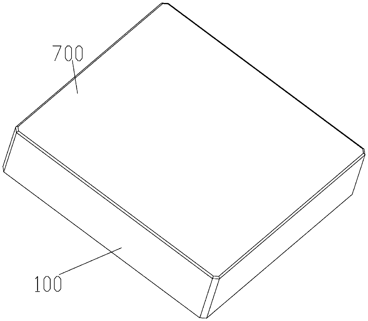
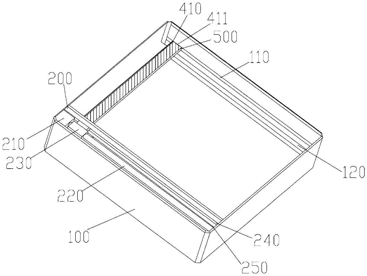
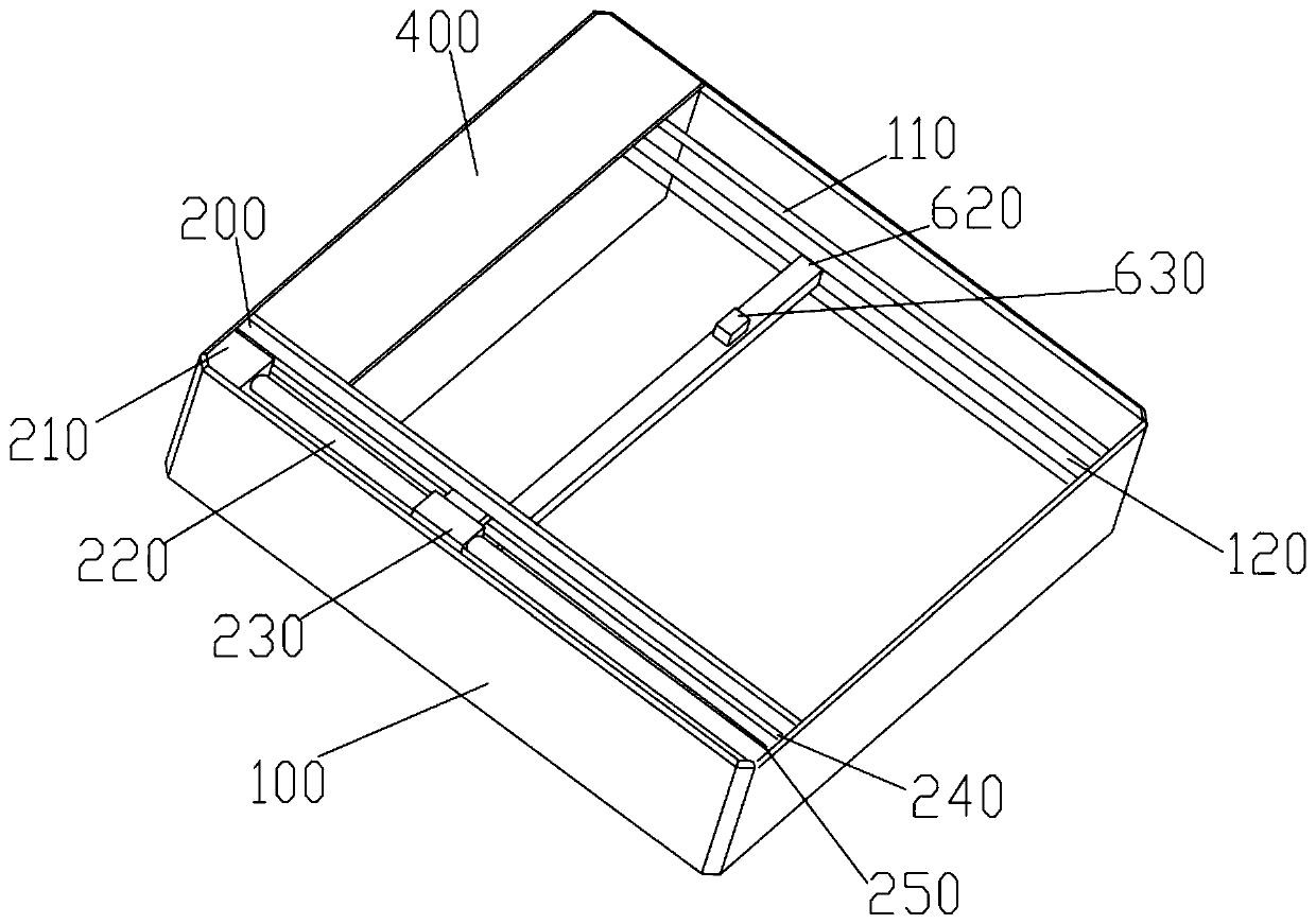
[0041] Such as Figure 1-5 As shown, the present invention provides a wireless charging device for automatic directional transmission, including: a base, a scanning system disposed in the base, a displacement mechanism for moving the transmitting coil, a light-transmitting plate, and a controller.

[0042] The base 100 is a cavity structure, and the base 100 is provided with at least one single-axis moving mechanism for moving the transmitting coil. The transmitting coil is arranged laterally on the moving end of the single-axis moving mechanism, and the transmitting coil can be changed by controlling the single-axis moving mechanism. The transmitting coil is connected to the power supply through a driver, and the driver controls the excitation of the transmitting coil to generate an alternating magnetic field, so that the receiving coil receives and generates electric energy for charging the device to be charged, and the driver is provided with a power A monitoring unit to mo...

Embodiment 2

[0066] The difference from Embodiment 1 is that, if Figure 6-8 As shown, three uniaxial moving mechanisms 620, 640 and 660 with the same structure are provided. The uniaxial moving mechanisms 640 and 660 are arranged on both sides of the uniaxial moving mechanism 620. The base at the second end of the sliding plate in the width direction is provided with In the second accommodation cavity 300, it can be understood that a plurality of single-axis moving mechanisms can be provided as required, and a second positioning cavity is opened at the first end of each single-axis moving mechanism in the length direction.

[0067]A transmitting coil is respectively arranged on the moving end 630 of the single-axis moving mechanism 620 , the moving end 650 of the single-axis moving mechanism 640 and the moving end 670 of the single-axis moving mechanism 660 . At the initial position, the single-axis moving mechanism 660, the single-axis moving mechanism 620 and the sliding plate 500 are a...

Embodiment 3

[0074] The difference from Embodiment 2 is that the transmitting coil includes several groups of concentric coils with different inner diameters, each concentric coil is coaxially arranged, each of the concentric coils is connected to the driver through a controllable switch, and the controllable switch The control terminal is connected to the controller.

[0075] Usually, the specifications of the receiving coils on each device to be charged are not fixed. Several coaxial concentric coils can be set according to the size of several conventional receiving coils. When the transmitting coil and receiving coil are aligned, the same excitation signal Under the premise, each controllable switch is switched one by one, and the receiving coil is excited and charged through different concentric coils. The power monitoring unit monitors the transmission power of each concentric coil in real time, and finally selects the concentric coil with the largest transmission power to excite and c...


PUM


Abstract

The invention discloses an automatic directional transmission wireless charging device. The wireless charging device comprises a base, and the upper part of the base is provided with a sliding board which is movable in the transverse direction. A first end sidewall of the sliding board in the length direction is provided with a first fixing chamber. The first end of the upper surface of the sliding board in the width direction is provided with a first lamp tube. The second end of the upper surface of the sliding board in the width direction is provided with a photosensitive detecting board. The automatic directional transmission wireless charging device further comprises the components of a plurality of single-axis moving mechanisms, wherein the first end sidewall of the single-axis movingmechanism in the length direction is provided with a second fixing chamber; a transmitting coil; a light-penetrable board; two telescopic driving mechanisms which are separately arranged in a lineardriving mechanism, wherein the telescoping end of the first telescopic driving mechanism selectively extends into the first fixing chamber, and the telescoping end of the second telescopic driving mechanism selectively extends into the second fixing chamber; and a controller which is connected with the lamp tube, the photosensitive sensing board, the driver, the linear driving mechanism and the telescopic driving mechanism. The automatic directional transmission wireless charging device settles a technical problem of easy dislocation between a transmitting coil and a receiving coil in the wireless charging device.

Description

technical field [0001] The invention relates to the technical field of wireless charging, in particular to a wireless charging device for automatic directional transmission. Background technique [0002] At present, the most common charging solution uses electromagnetic induction. By applying an alternating current of a certain frequency to the primary coil, a certain current is generated in the secondary coil through electromagnetic induction, thereby transferring energy from the transmission end to the reception end, thereby providing The charging device performs wireless charging. [0003] However, there is a defect in the current electromagnetic induction wireless charging method. It is necessary to align the transmitting coil with the receiving coil to achieve an efficient wireless charging process. When the transmitting coil and the receiving coil are slightly deviated, it will cause power transmission efficiency. However, when the user is charging the charging device...

Claims


Application Information

Patent Timeline
Patent Type & Authority Patents(China)
IPC IPC(8): H02J50/90H02J50/10H02J50/40
CPCH02J50/10H02J50/40H02J50/90
Inventor 张敬林李垣江田雨波魏海峰
Owner NANJING UNIV OF INFORMATION SCI & TECH
Learn More