
Phosphogypsum floor heating box

A phosphogypsum and floor heating technology, applied in central heating components, household heating, space heating and ventilation details, etc., can solve problems such as potential safety hazards, increased energy consumption, damage to floor heaters, floor heater damage, etc., to achieve Easy to buy, save electricity, fast heating effect

Pending Publication Date: 2020-11-17
GUIZHOU KAILIN PHOSPHOGYPSUM INTEGRATION UTILIZATION +1
View PDF0 Cites 0 Cited by
  • Summary
  • Abstract
  • Description
  • Claims
  • Application Information

AI Technical Summary

Problems solved by technology

[0002] With the improvement of people's material living standards, floor heating equipment is widely used in various civil buildings. In the cold winter, people use floor heating equipment for heating. Existing floor heating equipment generally uses heating wires to heat and emit heat. However, this kind of floor heating equipment has the following defects in use: First, because this type of floor heater needs to occupy a certain space in the room when it is used and placed, when the user walks in the room, it is easy to bump into the floor heater. , so that the floor heater causes damage or burns to the corresponding parts of the user's body; second, this type of floor heater converts electrical energy into heat energy for the user to use. To increase the heating power of the floor heater, it is necessary to increase the heating power of the corresponding heating wire. The corresponding safety hazards and energy consumption also increase accordingly, and the economy is poor

Method used


Image

  • Phosphogypsum floor heating box
  • Phosphogypsum floor heating box
  • Phosphogypsum floor heating box

Examples


Embodiment Construction

[0020] The technical solution of the present invention is further described below, but the scope of protection is not limited to the description.

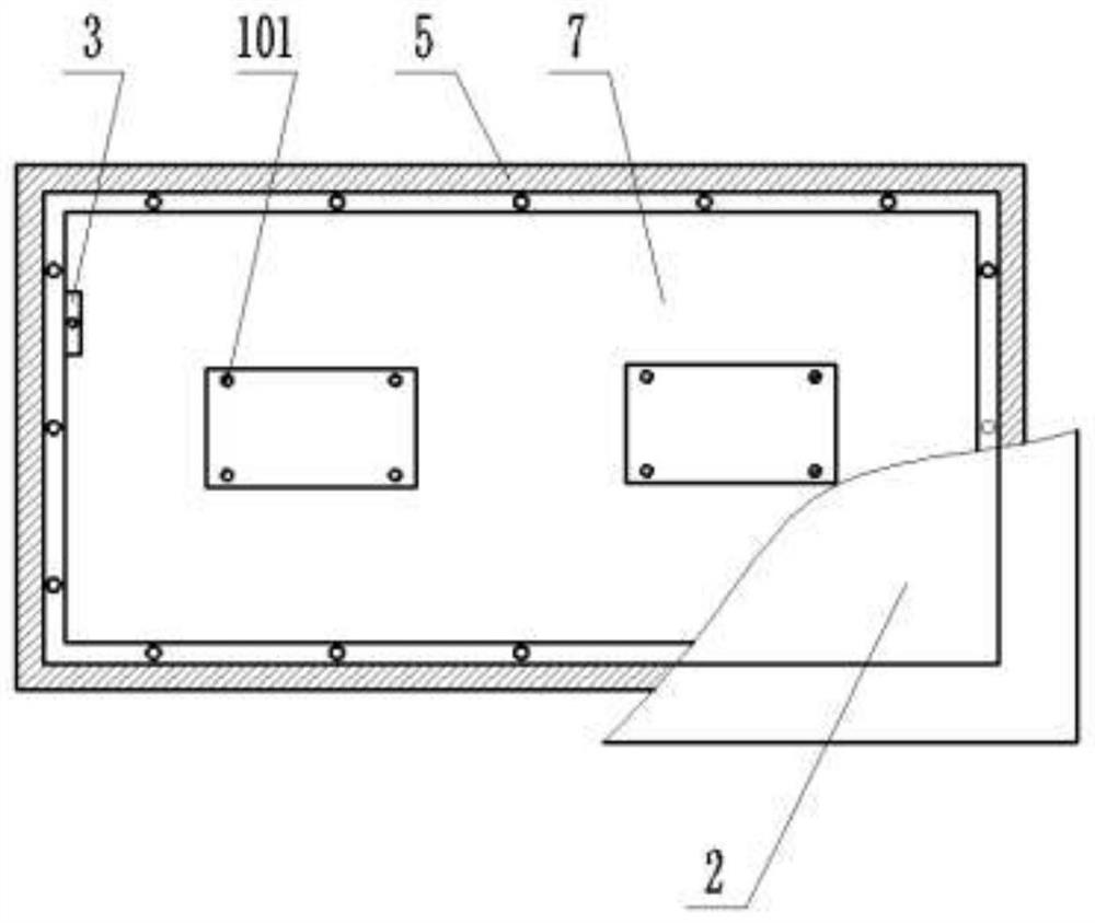
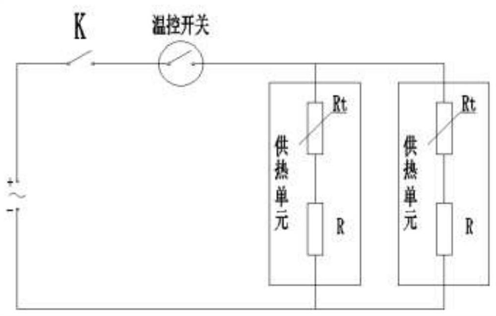
[0021] Such as figure 1 , figure 2 , image 3 As shown, the present invention provides a phosphogypsum floor heating oven, which includes a mica heating plate 1, a floor heating plate 2, a proximity switch 3, a control device 4, and a box body 5 with an opening at the top. The floor heating plate 1 is made of phosphogypsum material and passed through a press It is integrally pressed and formed. The open end of the box body 5 is provided with a step 501. Several proximity switches 3 are installed on the edge of the step 501. The floor heating plate 2 is placed on the step 501 and the open end of the box body 5 is covered. The mica heating plate 1 is installed Inside the box body 5 , the control device 4 is installed on the outer wall of the box body 5 , and the proximity switch 3 and the proximity switch 3 are both electrically c...


PUM


Abstract

The invention relates to a phosphogypsum floor heating box. The phosphogypsum floor heating box comprises mica heating plates, floor heating plates, proximity switches, a control device and a box bodywith an opening in the top end, the floor heating plates are integrally formed by pressing phosphogypsum materials through a press machine, steps are arranged at the opening end of the box body, andthe multiple proximity switches are installed at the edges of the steps; and the floor heating plates are arranged on the steps in a lap joint manner and cover the opening end of the box body, the mica heating plates are installed in the box body, the control device is installed at the outer wall of the box body, and the proximity switch and the proximity switch are electrically connected with thecontrol device. According to the technical scheme, the floor heating plates are made of the phosphogypsum, the application field of the phosphogypsum is expanded, the dissipation speed of heat energygenerated by the mica heating plates is decreased through the floor heating plates, the heat preservation effect is improved, a user cannot make direct contact with the mica heating plates, the useris prevented from being scalded, and safety is improved; and when the user leaves, the phosphogypsum floor heating box is automatically stopped, usage by the user is facilitated, and electric energy is saved.

Description

technical field [0001] The invention belongs to the technical field of floor heating equipment, in particular to a phosphogypsum floor heating oven. Background technique [0002] With the improvement of people's material living standards, floor heating equipment is widely used in various civil buildings. In the cold winter, people use floor heating equipment for heating. Existing floor heating equipment generally uses heating wires to heat and emit heat. However, this kind of floor heating equipment has the following defects in use: First, because this type of floor heater needs to occupy a certain space in the room when it is used and placed, when the user walks in the room, it is easy to bump into the floor heater. , so that the floor heater causes damage or burns to the corresponding parts of the user's body; second, this type of floor heater converts electrical energy into heat energy for the user to use. To increase the heating power of the floor heater, it is necessary...

Claims


Application Information

Patent Timeline
Patent Type & Authority Applications(China)
IPC IPC(8): F24D13/02F24D19/00F24D19/10F24D19/06
CPCF24D13/024F24D19/00F24D19/1096F24D19/06F24D2200/08F24D2220/2036
Inventor 姚孟林杨淑芬韦明志安光文杨步雷杨永彬张启卫彭步平崔俊新宋维相徐韦洪李贵汶朱国飞王琴何珍张燕施辉朝米林徐虎刘小成罗进峰赵先明陈剑
Owner GUIZHOU KAILIN PHOSPHOGYPSUM INTEGRATION UTILIZATION
Learn More