Optometry lens box

A lens and box technology, applied in the field of optometry lens boxes, can solve the problems of affecting optometry accuracy, low optometry efficiency, wrong lenses, etc., and achieves the effect of eliminating optometry errors, reducing optometry error rates, and avoiding taking errors.

Pending Publication Date: 2018-08-10
北京幸福远见医疗科技集团有限公司
View PDF0 Cites 0 Cited by
  • Summary
  • Abstract
  • Description
  • Claims
  • Application Information

AI Technical Summary

Problems solved by technology

[0002] At present, the trial lenses used in ophthalmology optometry mainly include positive spherical lenses, negative spherical lenses, positive cylindrical lenses, negative cylindrical lenses, prism lenses, auxiliary lenses, etc. Since the external shapes of each trial lens are the same, it is easy to cause gaps between the lenses. Confused with each other, thus affecting the accuracy of optometry
[0003] In order to prevent these lenses from being confused with each other, optometrists often need to spend a long time searching and comparing, which has the problems of inconvenient picking and placing of optometry lenses and low optometry efficiency; in addition, in actual optometry, often need to Pick and place a variety of optometry lenses to selectively use optometry lenses. Due to the large number of lenses, it is inevitable that there will be misplaced lenses during the picking process, which will seriously affect the correctness of optometry prescriptions and diagnostic results. sexual problems

Method used


Image

  • Optometry lens box
  • Optometry lens box
  • Optometry lens box

Examples


no. 1 example

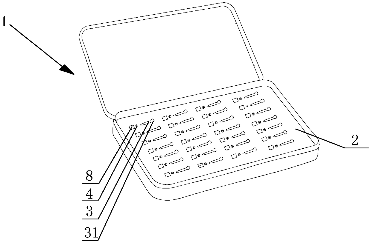
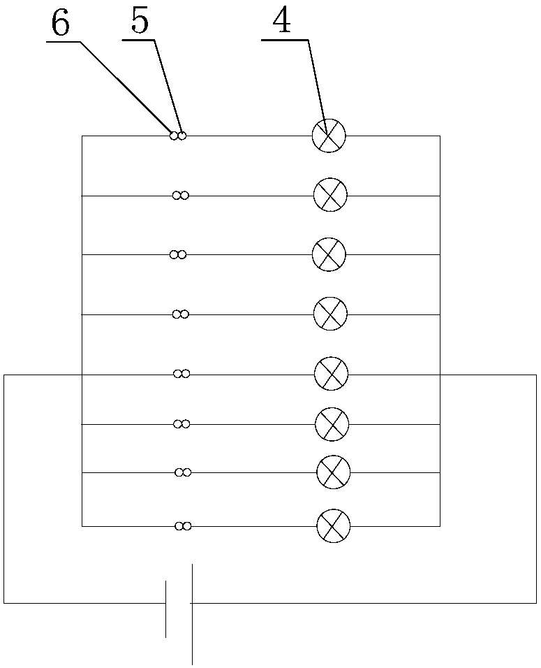
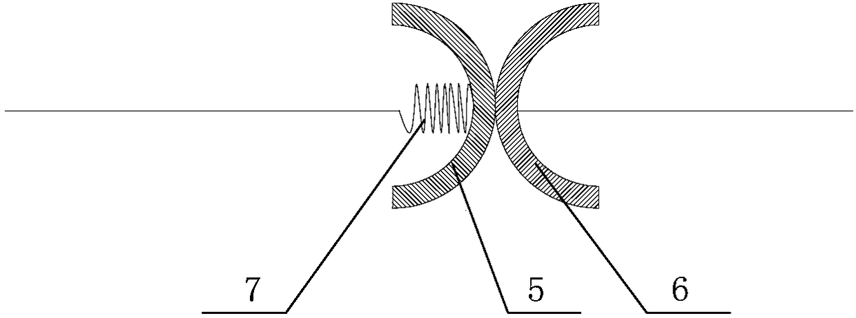
[0052] figure 1 It is a schematic diagram showing the overall structure of the first embodiment of the prescription lens case provided by the present invention. figure 2 It is a schematic diagram showing the structure of the indicating circuit of the first embodiment of the prescription lens box provided by the present invention. image 3 It is a schematic diagram showing the connection structure between the first circuit conducting sheet and the second circuit conducting sheet in the indicating circuit of the first embodiment of the prescription lens case provided by the present invention.

[0053] Such as Figure 1 to Figure 3 As shown, the trial lens case includes a case body 1 .

[0054] Inside the box body 1 is provided with a base plate 2 for placing trial lenses, on the base plate 2 are provided with a plurality of placement recesses 3 for placing different types of trial lenses, and each placement recess 3 is provided with its own indicating circuit.

[0055] Each...

no. 2 example

[0067] Figure 4 It is a schematic diagram showing the connection structure between the first circuit conducting sheet and the second circuit conducting sheet in the indicating circuit of the second embodiment of the prescription lens case provided by the present invention.

[0068] On the basis of the first embodiment, compared with the first embodiment, "more specifically, in each indicating circuit, the first circuit conduction sheet 5 and the second circuit conduction sheet 6 are respectively formed as an arc shape, and the first circuit conducting sheet 5 and the second circuit conducting sheet 6 are respectively bent in directions away from each other.

[0069] At least one of the first circuit conducting sheet 5 and the second circuit conducting sheet 6 is connected to the electric wire indicating the circuit through a conductive spring 7, for example, as image 3 As shown, the first circuit conduction piece 5 is connected to the electric wire of the indicating circuit...

no. 3 example

[0076] Figure 5 It is a schematic diagram showing the connection structure between the first circuit conducting sheet and the second circuit conducting sheet in the indicating circuit of the third embodiment of the trial lens case provided by the present invention.

[0077] On the basis of the first embodiment, compared with the first embodiment, "more specifically, in each indicating circuit, the first circuit conduction sheet 5 and the second circuit conduction sheet 6 are respectively formed as an arc shape, and the first circuit conducting sheet 5 and the second circuit conducting sheet 6 are respectively bent in directions away from each other.

[0078] At least one of the first circuit conducting sheet 5 and the second circuit conducting sheet 6 is connected to the electric wire indicating the circuit through a conductive spring 7, for example, as image 3 As shown, the first circuit conduction piece 5 is connected to the electric wire of the indicating circuit through...


PUM


Abstract

The invention relates to an optometry lens box. The box comprises a box body, a substrate is arranged in the box body, a plurality of placing grooves used for placing optometry lenses of different kinds are formed in the substrate, respective indicating circuits of the placing grooves are arranged in each placing groove, each indicating circuit comprises a power supply, an indicating lamp arrangedon the outer part of the placing groove, a first circuit conducting sheet internally arranged in the placing groove and a second circuit conducting sheet, the indicating lamp, the first circuit conducting sheet and the second circuit conducting sheet are in serial connection and connected with the power supply to form a closed loop, insulation protrusions are arranged at the edges of each optometry lens, and the arrangement positions of the insulation protrusions of each optometry lens along the edges of the optometry lenses are different. By means of the box, whether or not the optometry lenses are correctly placed in the box body is displayed through the indicating circuits to avoid disorders among the optometry lenses to improve the optometry efficiency, and meanwhile mistakenly takingof the optometry lens is avoided, so that optometry error is reduced, and the correctness of an optometry result is ensured.

Description

technical field [0001] The invention relates to the field of ophthalmic optometry equipment, in particular to an optometry lens case. Background technique [0002] At present, the trial lenses used in ophthalmology optometry mainly include positive spherical lenses, negative spherical lenses, positive cylindrical lenses, negative cylindrical lenses, prism lenses, auxiliary lenses, etc. Since the external shapes of each trial lens are the same, it is easy to cause gaps between the lenses. Confused with each other, thus affecting the accuracy of optometry. [0003] In order to prevent these lenses from being confused with each other, optometrists often need to spend a long time searching and comparing, which has the problems of inconvenient picking and placing of optometry lenses and low optometry efficiency; in addition, in actual optometry, often need to Pick and place a variety of optometry lenses to selectively use optometry lenses. Due to the large number of lenses, it i...

Claims


Application Information

Patent Timeline
IPC IPC(8): A61B3/00A61B50/31
CPCA61B3/00A61B50/31A61B2050/0051
Inventor 李小丹
Owner 北京幸福远见医疗科技集团有限公司
Why Eureka
Try Eureka