

Fabricated platform
A prefabricated and platform technology, which is applied in the direction of building structure support, building structure support, building structure support scaffolding, etc., can solve the problem of inconvenient adjustment of the length of the platform protruding from the floor plate, and achieve convenient and reliable adjustment and fixing, ensuring safety sexual effect
- Summary
- Abstract
- Description
- Claims
- Application Information
AI Technical Summary
Problems solved by technology
Method used
Image

Examples
Embodiment 1
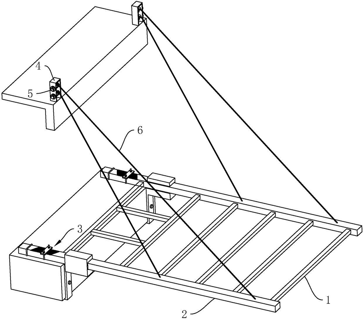
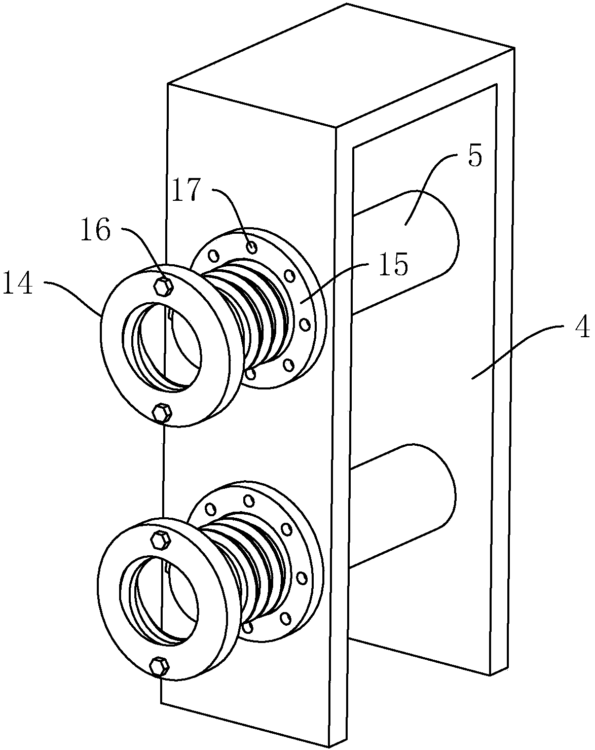
[0034] Embodiment 1: a kind of prefabricated platform, such as figure 1 with figure 2 As shown, it includes a platform 1 and a cable support mechanism; the two main beams 2 of the platform 1 are provided with ground anchor rings 3 for fixing the main beam 2 on the building; the building is fixedly provided with a mounting frame 4 The stay cable supporting structure includes a reel 5 arranged horizontally and rotatably connected to the installation frame 4 and a stay rope 6 whose upper end is fixedly connected to the reel 5, the lower end of the stay rope 6 is fixedly connected to the front end of the main beam 2, and the reel 5 is equipped with a The locking mechanism fixed by the mounting frame 4.
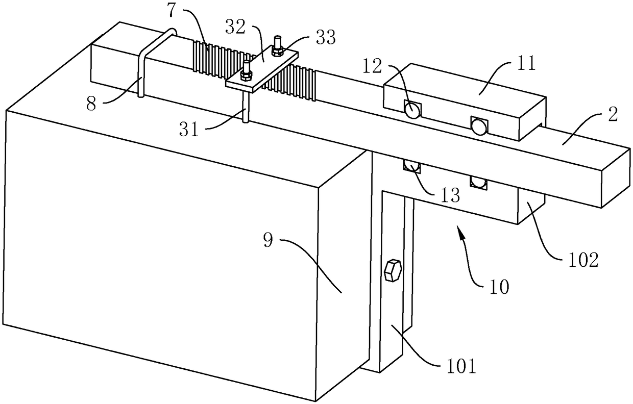
[0035] The ground anchor ring 3 includes a "U"-shaped positioning ring 31 fixedly arranged on the floor slab. The rear end of the main beam 2 passes through the positioning ring 31. The positioning ring 31 is inserted with a horizontal positioning steel plate 32. The positioning...
Embodiment 2
[0044] Embodiment 2: a kind of prefabricated platform, such as Figure 4 with Figure 5 As shown, the difference between it and Embodiment 1 is only that the structure of the locking mechanism is different, and the specific structure of the locking mechanism in this embodiment is:
[0045] It includes a locking gear 18 fixed on the reel 5, and a locking rack 19 that can be engaged with the locking gear 18 is horizontally slidably connected to the mounting frame 4, and a threaded rod 20 that is threaded through the locking rack 19 , the threaded rod 20 is arranged along the sliding direction of the locking rack 19 and is rotatably connected with the mounting frame 4 . Rotate screw mandrel 20, thereby drive locking rack 19 to slide and lock or unlock with locking gear 18, the fixing and unfixing of reel 5 is convenient and quick, safe and reliable.
[0046] Specific working process: When adjusting the position of the stand 1, turn the screw rod 20 to drive the locking rack 19 ...
PUM
 Abstract
Description
Claims
Application Information