
Well completion transformation casing head

A casing and casing technology, applied in the casing head field, can solve problems such as sealing structure performance and long-term disputes, increase the height of the wellhead exposed to the ground, and not accept well completion handover, etc., to achieve a safe operating environment and convenience, Reduce cutting phenomenon, save cost and time

Active Publication Date: 2018-08-10
CNPC BOHAI DRILLING ENG +1
View PDF8 Cites 6 Cited by
  • Summary
  • Abstract
  • Description
  • Claims
  • Application Information

AI Technical Summary

Problems solved by technology

[0003] (1) The structure of the slip casing head is complex, the manufacturing cost is high, and the sales price is higher. Users are generally limited to use in exploration wells with a large number of casing layers;
[0004] (2) The wellhead installation of the slip-type casing head takes a long time in the later stage of the cementing operation. The waiting time is long, and the wellhead device of the blowout preventer needs to be repeatedly disassembled and installed. The operation is troublesome and there are many safety risks;
[0005] (3) The slip-type casing head is connected to the casing by cutting the casing body before the well completion is handed over. The injection-molded sealing structure is used to connect with the casing body. For the injection-molding sealing structure, special tools and tools are required. On-site service by technicians, with a lot of content, cumbersome operation, complicated replacement operation in the later stage, and the performance and durability of the sealing structure are still controversial;
[0006] (4) The wellhead configuration of the slip-type casing head only meets the flange (unique) form, which makes it inconvenient to replace the connection mode in the later production and transportation operations;
[0007] (5) The mandrel type casing head requires accurate control of the position of the mandrel hanger, which increases the difficulty for the operator to select and match the casing string for entering the well, especially the running position of the last casing must ensure the suspension The device can be accurately set and sealed at the flange design position of the casing head body, otherwise abnormal working conditions will occur and subsequent processing is cumbersome;
[0008] (6) With the increase of directional well types and horizontal well types, the phenomenon of weight loss of casing strings in the cement slurry in the wells increases, causing the hanger to fail to set the design position of the casing head. Drilling users are very difficult to face this phenomenon. The on-site maintenance process of the dealer is complicated, and the repair cost is high;
[0009] (7) The connection between the mandrel hanger and the casing of the mandrel casing head has the problem of excessive short joints of the mandrel. Because the materials of the mandrel short joints and the casing are different, it is easy to cause sticking or other damage. The cause of the damage Many disputes and disputes are formed due to poor identification, which directly affects the use and sales of casing head products in the later stage;
[0010] (8) The completion wellhead of the mandrel hanger is also connected by female thread. The treatment technology for female thread damage is very troublesome, and it is very inconvenient to use electricity and gas welding. There are risks to safety and welding quality, and it will increase the height of the wellhead exposed to the ground. It will add a lot of cost to the surface engineering of the post-production operation, and it is difficult for Party A to accept or not accept the completion handover at all;
[0011] (9) For the completion wellhead with female thread connection, when installing a Christmas tree or other engineering operation devices, it is necessary to equip a male thread nipple, and the Christmas tree device itself is a flange connection, so this conversion is a bit redundant. Excessive pup joints form a top-heavy shape, causing a lot of damage to the thread, especially making up and breaking down many times will accelerate the thread damage, and the same consequences as items (7) and (8) will appear

Method used


Image

  • Well completion transformation casing head
  • Well completion transformation casing head
  • Well completion transformation casing head

Examples


Embodiment Construction

[0101] It should be noted that, in the case of no conflict, the embodiments of the present invention and the features in the embodiments can be combined with each other.

[0102] In describing the present invention, it should be understood that the terms "center", "longitudinal", "transverse", "upper", "lower", "front", "rear", "left", "right", " The orientations or positional relationships indicated by "vertical", "horizontal", "top", "bottom", "inner" and "outer" are based on the orientations or positional relationships shown in the drawings, and are only for the convenience of describing the present invention and Simplified descriptions, rather than indicating or implying that the device or element referred to must have a particular orientation, be constructed and operate in a particular orientation, and thus should not be construed as limiting the invention. In addition, the terms "first", "second", etc. are used for descriptive purposes only, and should not be understood ...


PUM


Abstract

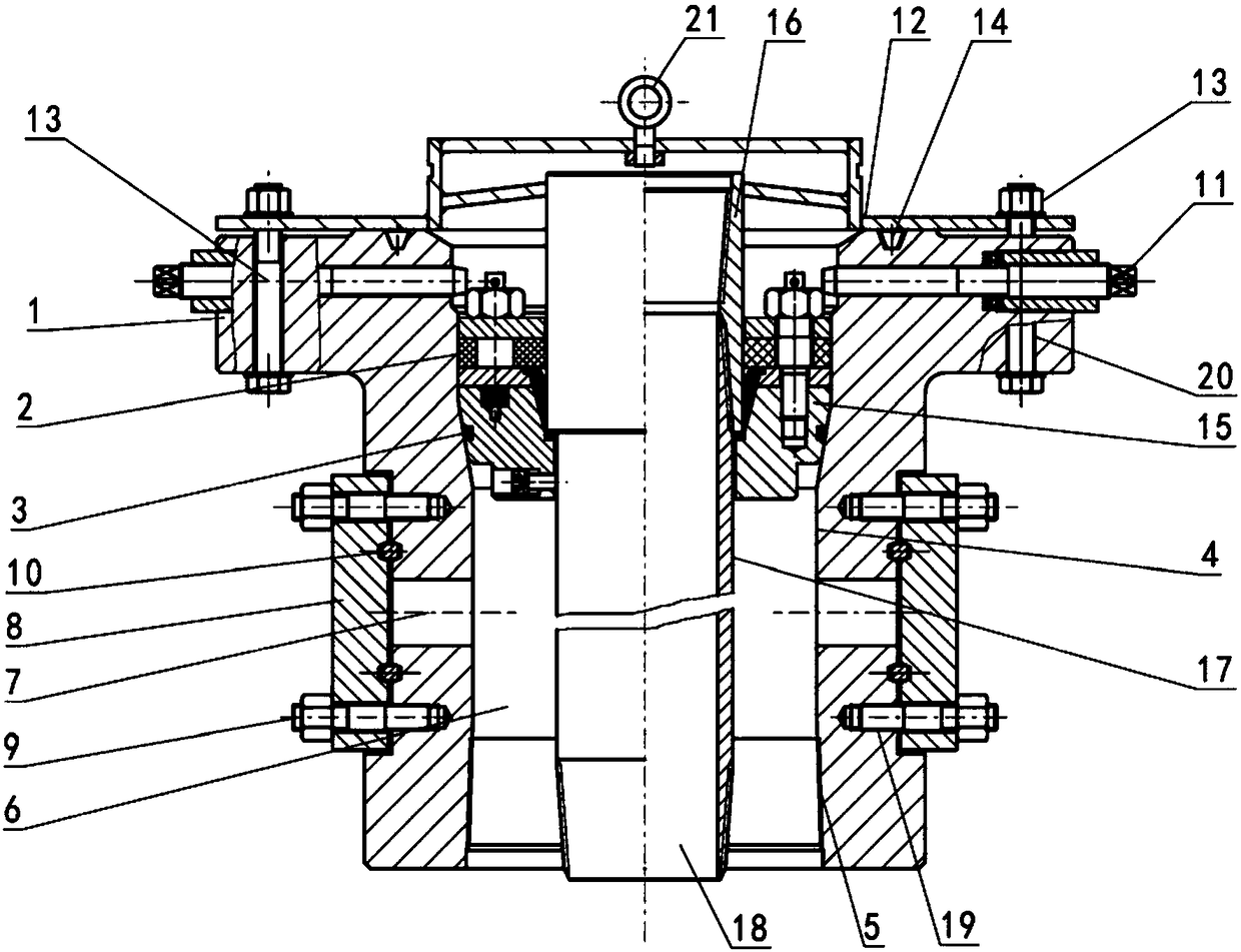
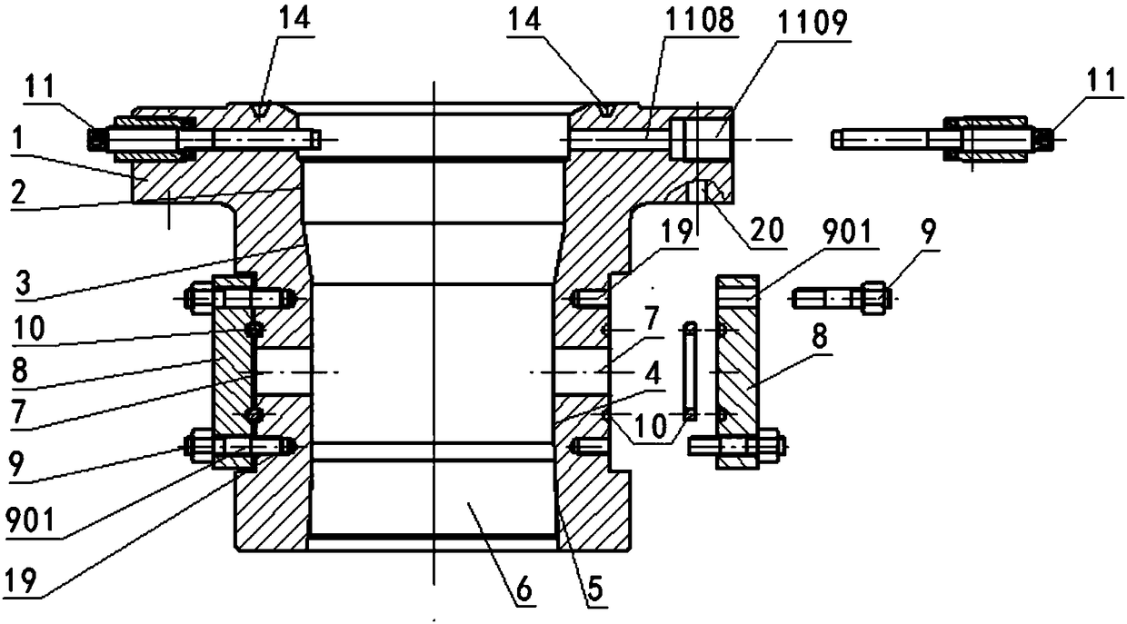
The invention relates to a well completion transformation casing head. An overall structure of the casing head integrates the advantages of a mandrel casing head and a slip casing head. More transformation connecting, sealing and mounting structures and the like for a complicated completion wellhead are formed based on a coupling casing head structure; multiple connecting and mounting plans are predesigned according to possible wellhead complexity on site; for example, a casing coupling hanger in a coupling casing head is transformed into a casing body hanger with higher generality; for another example, the advantage of a BT sealing technology is integrated into a special transformation wellhead sealing flange; a composite sealing structure such as a special sealing element is derived; andfor another example, the transformation wellhead sealing flange and the special transformation wellhead sealing flange are applicable to common standard transformation structures such as a standard flange, non-standard double flanges, a non-standard welding flange and a non-standard threaded flange in a completion process.

Description

technical field [0001] The invention belongs to the field of casing head technology, and in particular relates to a casing head which can be changed for well completion. Background technique [0002] The casing head product is the wellhead guarantee condition that must be provided in oil and gas well drilling and production and transportation operations. It mainly meets the need to install wellhead blowout preventers in order to prevent "blowout" in drilling operations, and to provide effective wellhead connections for production and transportation operations. It provides a safe, efficient and convenient way to connect the ground and underground effectively for various engineering operations. In the development history of casing head products, we have experienced a lot of research and innovation. The structural characteristics of the product itself are inseparable from the connection with the casing string in the well. However, with the innovation of drilling technology, the...

Claims


Application Information

Patent Timeline
Patent Type & Authority Applications(China)
IPC IPC(8): E21B33/04
CPCE21B33/0422
Inventor 谭晓江李丽红李彬杜林王峰夏兴玉贾军王钢尹德森张川
Owner CNPC BOHAI DRILLING ENG
Learn More