Infrared continuous zooming optical system with large relative aperture and high zoom ratio

A technology of relative aperture and optical system, applied in optics, optical components, instruments, etc., can solve the problems of complex zoom optics and small relative aperture, and achieve the effect of reducing lens weight, improving off-axis aberration, and reducing costs.

Pending Publication Date: 2018-08-10
SHANGHAI INST OF TECHNICAL PHYSICS - CHINESE ACAD OF SCI
View PDF2 Cites 12 Cited by
  • Summary
  • Abstract
  • Description
  • Claims
  • Application Information

AI Technical Summary

Problems solved by technology

[0007] In order to solve the problem that the zoom ratio of the existing large relative aperture infrared continuous zoom optical system matched with the cooled detector is generally lower than 30 times, and the F number of the zoom system with a high zoom ratio cannot be less than 4, so that the relative aperture is too small, and the zoom The optical type is complex and difficult to realize by optical-mechanical engineering. The present invention provides an infrared continuous zoom optical system type that can be applied to cooling infrared detectors, the F number is constant at 2, and the zoom ratio is higher than 50 times.

Method used


Image

  • Infrared continuous zooming optical system with large relative aperture and high zoom ratio
  • Infrared continuous zooming optical system with large relative aperture and high zoom ratio
  • Infrared continuous zooming optical system with large relative aperture and high zoom ratio

Examples


Embodiment Construction

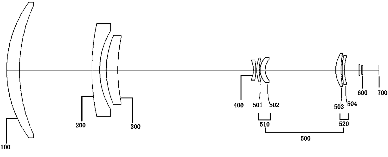
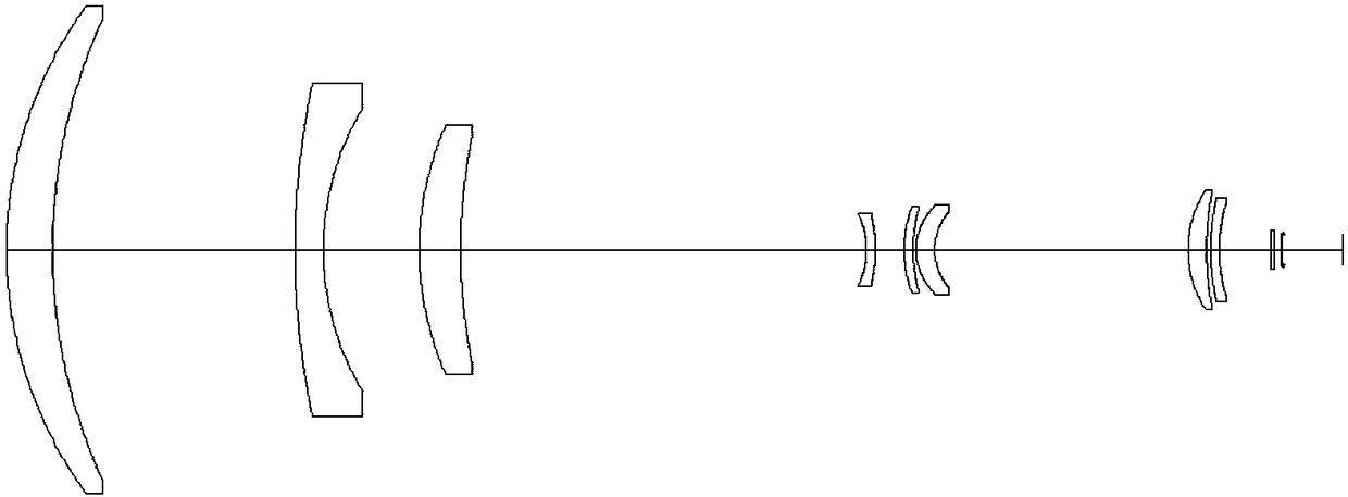
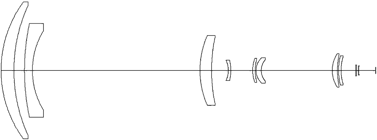
[0032] According to attached figure 1 As shown in the schematic diagram of , the infrared continuous zoom optical system with large relative aperture and high zoom ratio of the present invention has a focal length range of 6 mm to 330 mm, and a field of view coverage of 91.4 degrees to 2.1 degrees. In the entire zoom range, the F number is constant. 2. The total length of the entire optical axis is fixed at 460 mm. figure 1 , figure 2 , image 3 They are the schematic diagrams of the telephoto 330 mm, the medium focal length 168 mm, and the short focal length 6 mm.

[0033] The light beam from the object side passes through the front fixed lens group 100, the first variable power lens group 200, the compensation lens group 300, the second variable power lens group 400, and the rear fixed lens front group 510 (including the fifth lens 501 and the sixth lens group). lens 502 ), a relay imaging lens group 520 (including the seventh lens 503 and the eighth lens 504 ), a Dewar...


PUM


Abstract

The present invention discloses an infrared continuous zooming optical system with a large relative aperture and a high zoom ratio. The system comprises in order from an object surface to an image surface: a front fixed lens set, a first zooming lens set, a compensation lens set, a second zooming lens set and a rear fixed lens set. In the zooming process, the first zooming lens set, the compensation lens set and the second zooming lens set are continuously arranged in order, and a high zoom ratio exceeding 50 times and a relative aperture with F being constantly 2 can be obtained at the same time in a mode for separated motion front and back along an optical axis. The zooming optical type is concise, the zooming track is smooth, fixed components and motion components can be separately installed, regulated and located for easy implementation of an optical machine engineering. The infrared continuous zooming optical system can perform continuous zooming, is large in zoom ratio, large inrelative aperture, few in the number of lenses and high in energy collection, is especially suitable for a zooming system with medium waves of 3-5[Mu]m and infrared bands of 8-12 [Mu]m and can achieve100% cold light aperture matching.

Description

Technical field: [0001] The invention relates to an infrared thermal imaging optical system, in particular to an infrared continuous zoom optical system with a large relative aperture and a high zoom ratio. Background technique: [0002] Infrared zoom optical system includes two forms of step zoom and continuous zoom. According to the different detectors used, it can be divided into infrared zoom optical system with cooled detector and infrared zoom optical system with uncooled detector. . Among them, the infrared optical system with continuous zoom can realize the continuous change of the size of the scene during the zooming process, effectively avoiding the problem of losing fast-moving targets when the sub-level zoom is switched between fields of view, and can realize continuous imaging, which has higher application value . The infrared continuous zoom optical system combined with the cooling detector not only meets the needs of searching for targets in a large field of...

Claims


Application Information

Patent Timeline
Patent Type & Authority Applications(China)
IPC IPC(8): G02B15/16
CPCG02B15/16
Inventor 于洋潘兆鑫周潘伟丁学专
Owner SHANGHAI INST OF TECHNICAL PHYSICS - CHINESE ACAD OF SCI
Why Eureka
Try Eureka