Fluid gear type internal combustion engine
A gear type, internal combustion engine technology, applied to internal combustion piston engines, combustion engines, mechanical equipment, etc., can solve the problems of low work efficiency of internal combustion engines
- Summary
- Abstract
- Description
- Claims
- Application Information
AI Technical Summary
Problems solved by technology
Method used
Image

Examples
Embodiment 1
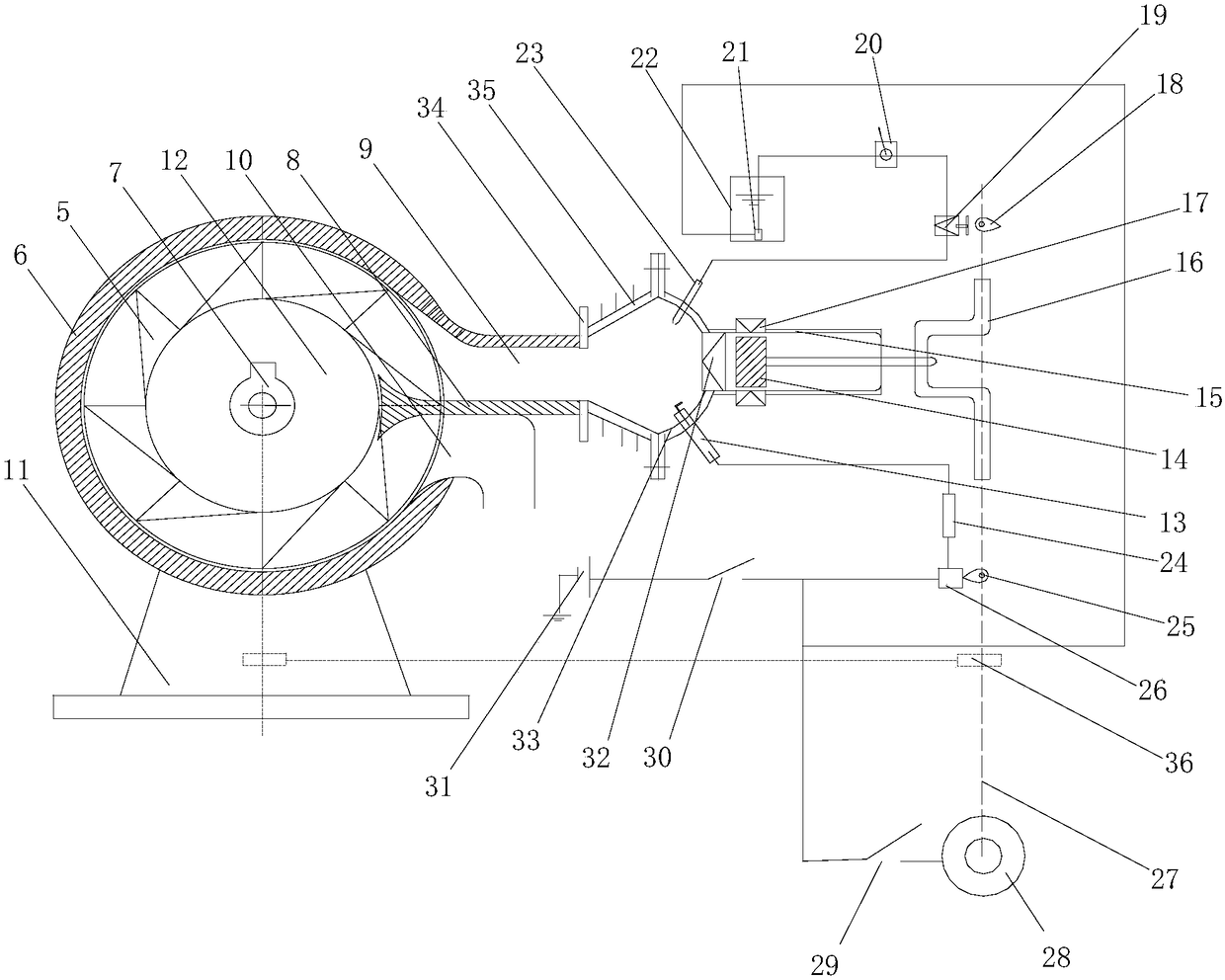
[0033] Such as Figure 1~5 As shown, the present embodiment includes a fluid machine and a burner. The fluid machine includes a housing 6, a fluid chamber is arranged in the housing 6, a rotating shaft 7 is arranged in the fluid chamber, and the fluid gear 12 is fixed on the On the rotating shaft 7, an opening communicating with the fluid chamber is provided on the outer wall of the housing 6, and the blocking partition 8 is fixed on the housing 6 and divides the opening into an inlet 9 and an outlet 10; the burner includes a cone cylinder 35 And crankshaft 16, and the two ends of described cone cylinder 35 are all open, are provided with cylinder 15 at an open end of described cone cylinder 35, and are provided with in cylinder 15 and are used for sealing off described cone cylinder 35 and the single To the intake valve 32, the piston 14 is slidably arranged in the cylinder 15, a connecting rod is hinged on the crankshaft 16, and the end of the connecting rod moves through th...
Embodiment 2
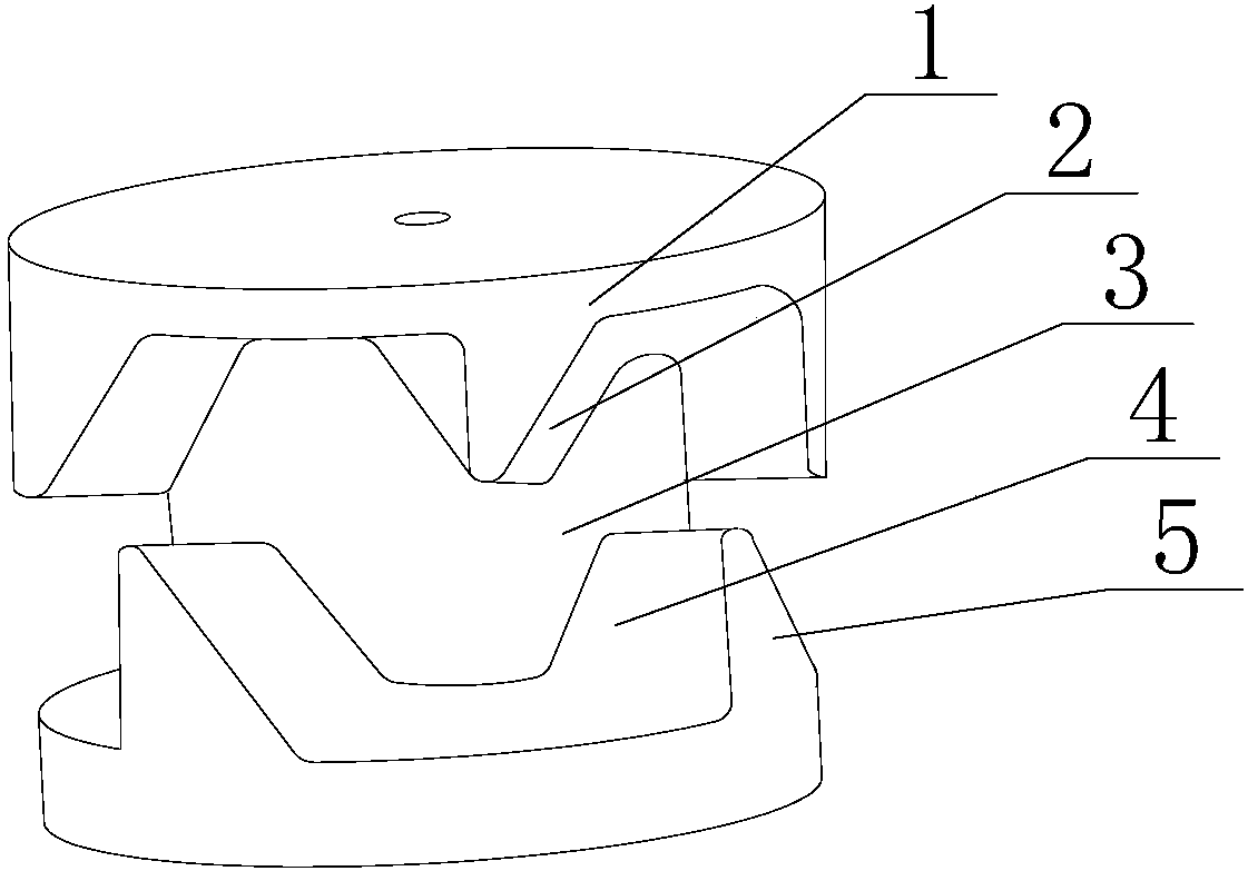
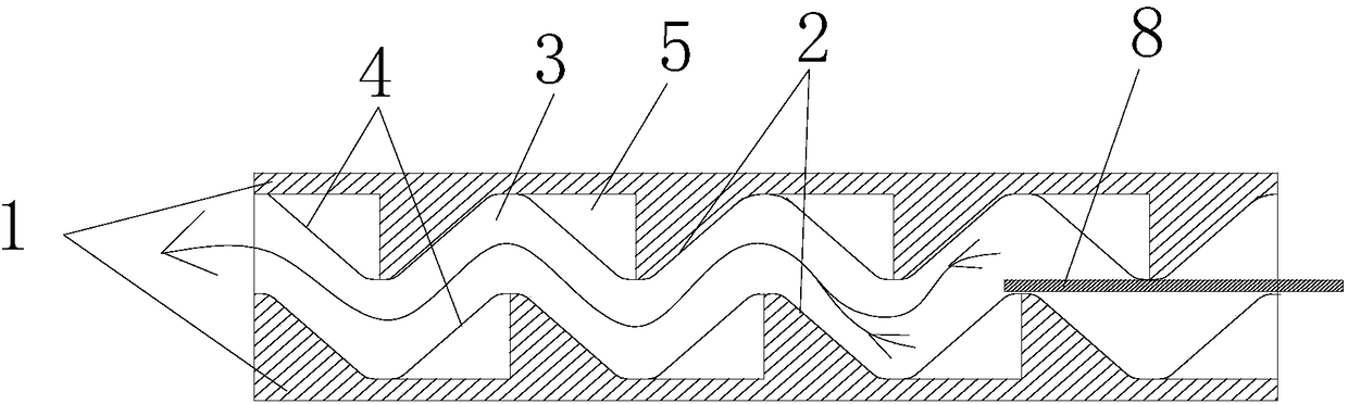
[0037] Such as Figure 1~5 As shown, this embodiment is based on Embodiment 1. The fluid gear 12 includes a cylinder 3, and two ribs 1 are provided on the outer peripheral wall of the cylinder 3 along the circumference of the cylinder 3, and each The inner side wall of the rib 1 is provided with a plurality of gear pieces 5, and any one of the ribs 1 is rotated along the circumference of the cylinder 3, so that the gear pieces 5 respectively located on the two ribs 1 are alternately distributed. Finally, an annular flow channel is formed between the two ribs 1 . This embodiment directly utilizes the high-temperature and high-pressure gas produced by the burner 16. After entering the fluid chamber through the inlet 9, it directly collides with the fluid gear 12 to drive the fluid gear 12 to rotate quickly, and then drives the generator 13 to work, that is, to realize mechanical energy. and electric energy, and when the gas moves to the outlet 10 of the housing 6, the gas does ...
Embodiment 3
[0041] Such as Figure 1~5 As shown, in this embodiment, on the basis of Embodiment 2, the tooth piece 5 is in the shape of a triangular block, and the inner side wall of the tooth piece 5 is connected to the outer side wall of the cylinder 3, and the bottom of the tooth piece 5 is connected to the rib 1 to the inner side wall connection. Further, the tooth piece 5 is fixed on the cylinder 3, and its inner side wall is completely attached to the outer peripheral wall of the cylinder 3, and the bottom of the tooth piece 5 is connected with the inner side wall of the sidewall 1, so that the tooth piece 5, the sidewall The side 1 and the cylinder 3 form a whole, and there is no gap between the tooth piece 5 and the cylinder 3, the tooth piece 5 is in the shape of an acute triangle block, so that when the gas impacts the tooth piece 5, there is an inclined and can directly contact with the gas, and the two rows of tooth pieces 5 are respectively distributed along the circumferenc...
PUM
 Abstract
Description
Claims
Application Information
 - R&D Engineer
- R&D Manager
- IP Professional
- Industry Leading Data Capabilities
- Powerful AI technology
- Patent DNA Extraction
Browse by: Latest US Patents, China's latest patents, Technical Efficacy Thesaurus, Application Domain, Technology Topic.
© 2024 PatSnap. All rights reserved.Legal|Privacy policy|Modern Slavery Act Transparency Statement|Sitemap