Squeeze-type circulation flow reaction vessel

A circulating flow, extrusion technology, applied in chemical/physical/physical chemical fixed reactors, cleaning hollow objects, chemical/physical/physical chemical processes, etc., can solve the problem of affecting the production efficiency of chemical products, long time , slow processing speed and other problems, to achieve the effect of increasing the mixing reaction rate, ensuring the mixing of raw materials, and improving the mixing efficiency

Inactive Publication Date: 2018-05-22
长沙德科投资管理咨询有限公司
View PDF2 Cites 15 Cited by
  • Summary
  • Abstract
  • Description
  • Claims
  • Application Information

AI Technical Summary

Problems solved by technology

At present, the reaction kettle commonly used by enterprises is composed of a kettle body, a motor, a stirring shaft and a stirring wheel. The motor is installed on the upper part of the kettle body. The wheel is connected vertically to the stirring shaft, and the motor drives the stirring shaft to rotate, so that the stirring wheel on the stirring shaft rotates rapidly to mix the materials. At present, when the existing reactor is stirring the material, it usually rotates in one direction. The stirring blade drives the material to rotate in the kettle body to achieve the purpose of material mixing. The mixing speed of this type of material is slow and the efficiency is low. It takes a long time for each stirring to make the material fully mixed, which affects the efficiency of chemical product production.

Method used


Image

  • Squeeze-type circulation flow reaction vessel
  • Squeeze-type circulation flow reaction vessel
  • Squeeze-type circulation flow reaction vessel

Examples


Embodiment Construction

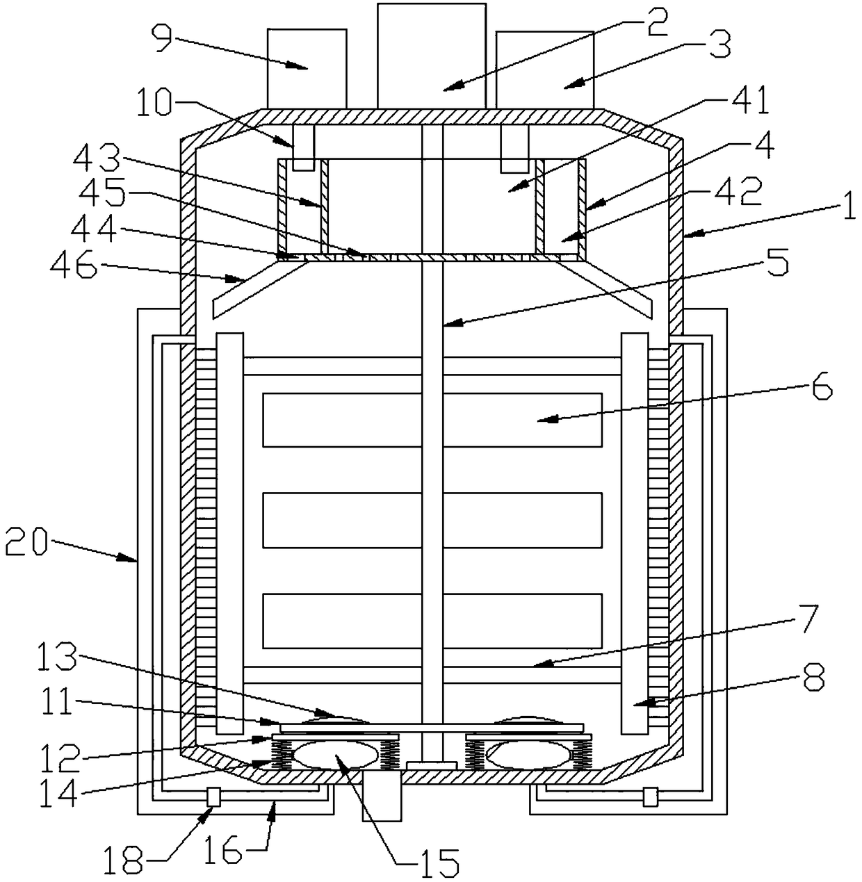
[0018] Please refer to the figure, in the embodiment of the present invention, a reaction kettle with extruding circulation flow includes a kettle body 1, a motor 2, a feed hopper 3, a stirring shaft 5 and a stirring blade 6; the motor 2 is fixedly installed in the kettle On the top of the body 1, the output shaft of the motor 2 extends vertically downward into the kettle body 1, and a vertical stirring shaft 5 is fixedly connected to the lower end of the output shaft of the motor 2, and the lower end of the stirring shaft 5 is connected to the kettle body through bearing rotation. At the bottom of the body 1, several stirring blades 6 are fixed on the stirring shaft 5, and the motor 2 drives the stirring shaft 5 to rotate, so that the stirring blades 6 can stir the inside of the kettle body 1; a horizontal rotating box is fixed on the stirring shaft 5 4. The central axis of the rotating box 4 coincides with the stirring shaft 5, and the rotating box 4 follows the rotation of t...


PUM


Abstract

The invention discloses a squeeze-type circulation flow reaction vessel, which comprises a vessel body, a motor, a feed hopper, an agitating shaft and agitating blades. A horizontal rotary case is fixedly arranged at the agitating shaft and is internally provided a loop of a baffle plate, wherein the baffle plate divides the rotary case into a central charging chamber and an external cleaning water chamber. The lower sides of first through-holes communicate with inclined liquid guiding pipes, which face the inner wall of the vessel body. Suction capsules are fixed at the bottom of the vessel body, and the upper ends of the suction capsules are fixedly attached to horizontal pressing plates. The upper surfaces of the pressing plates are provided with upward spherical projections in a fixedmanner. Rollers are installed on rotating shafts via bearings. Through the rotary case, a charged raw material is uniformly dispersed in the vessel body and is uniformly mixed inside. A circular ringrotates, and the upper rollers and the lower spherical projections continuously contact and are separated, so that the pressing plates located below the spherical projections move, and the suction capsules continuously suck a liquid located at the bottom of the vessel body.

Description

technical field [0001] The invention relates to a chemical equipment, in particular to an extrusion type circulating flow reaction kettle. Background technique [0002] Reactors are widely used in chemical industry, rubber, petroleum, dyestuff, medicine, food and other fields to complete the process of hydrolysis, polymerization, mixing, neutralization, hydrogenation, chlorination and other processes in the production process. At present, the reaction kettle commonly used by enterprises is composed of a kettle body, a motor, a stirring shaft and a stirring wheel. The motor is installed on the upper part of the kettle body. The wheel is connected vertically to the stirring shaft, and the motor drives the stirring shaft to rotate, so that the stirring wheel on the stirring shaft rotates rapidly to mix the materials. At present, when the existing reactor is stirring the material, it usually rotates in one direction. The mixing blade drives the material to rotate in the kettle ...

Claims


Application Information

Patent Timeline
Patent Type & Authority Applications(China)
IPC IPC(8): B01J19/18B01J4/00B08B9/08
CPCB01J19/18B01J4/001B01J19/0053B01J19/0066B08B9/08
Inventor 李彬彬
Owner 长沙德科投资管理咨询有限公司
Why Eureka
Try Eureka