A single-drive control invisible connection method

A connection method and single-drive technology, applied in the direction of connecting components, screws, threaded fasteners, etc., can solve the problems of complicated operation and affect the appearance, and achieve the effect of ensuring perfection and easy disassembly and assembly.

Active Publication Date: 2021-12-14
SUZHOU SABO IND DESIGN
View PDF8 Cites 0 Cited by
  • Summary
  • Abstract
  • Description
  • Claims
  • Application Information

AI Technical Summary

Problems solved by technology

[0002]Screws, bolts and other fasteners are widely used in various types of equipment, and have formed a complete series of standards and become general-purpose parts in the industry; but such fasteners Restricted by the way of operation, some fasteners need to be exposed by the working part to facilitate the disassembly and assembly of the working tools, which leads to the protruding of many fasteners being worked on the outside of the connected parts. In order to avoid interference with such Fasteners need to process corresponding process bottom holes on the connected parts, especially in the field of large wooden, rubber-plastic and aluminum parts. The traditional fastening connection method is not only cumbersome to operate but also affects the appearance; therefore, a new type of The fastening connection operation method can not only solve the seamless fastening of many large components, but also facilitate disassembly and assembly without affecting the appearance, so as to ensure the integrity of the original product design and the perfection of multi-part connection

Method used


Image

  • A single-drive control invisible connection method
  • A single-drive control invisible connection method
  • A single-drive control invisible connection method

Examples


Embodiment Construction

[0029] In order to make the techniques of the present invention, the creation characteristics, the purpose and efficacy are easy to understand, and the present invention is further illustrated in connection with the specific illustration.

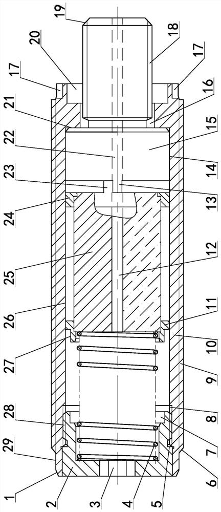
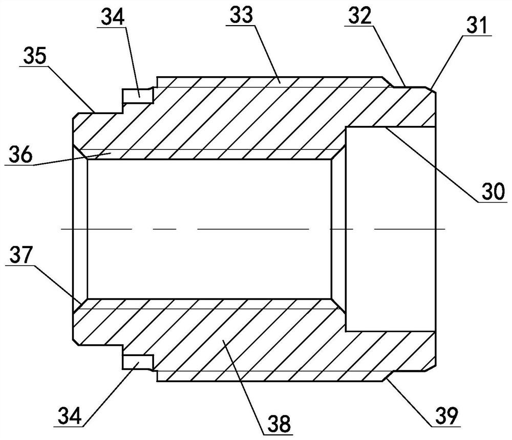
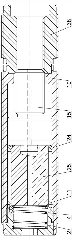
[0030] A single drive control invisible connection method, using single drive control invisible connection device to implement single-drive control invisible connection, see Figure 1 ~ 4 Single drive control stealth connection device, including the first guiding cone 1, the screw 2, the screw internal hexagon 3, the reset spring 4, the screw limit end surface 5, the second guiding cone 6, the second guide hole 7 However, the main drive is threaded 8, the main drive outer thread 9, the main driving body 10, the drive magnet rear end bracket 11, the first through hole 12, the driven convex pin 13, the body fitting the outer circle 14, the linker body 15, the main The drive connection channel 16, the main drive mounting groove 17, the hydraulic ex...


PUM


Abstract

A single-drive control invisible connection method, using a single-drive control invisible connection device to implement a single-drive control invisible connection, when the invisible connection is required, manually or electrically drive the installation drive separately through any drive connection port in the installation drive mechanism mechanism, so as to drive the driving magnet to rotate, the driven convex pin and the driving convex pin are fitted together for transmission, and the driving magnet drives the connecting bolt body to rotate through the active convex pin on the front bracket of the driving magnet, and the external thread of the bolt and the auxiliary bolt are pushed by the return spring. The internal thread is rotated and matched, and finally the auxiliary connecting body and the external thread of the main driver are tightened. At this time, the outer circle of the auxiliary body is connected with the inner cavity of the main driving body, and the invisible connection between the first connected body and the second connected body is realized; When the driving mechanism is installed in the reverse direction, the driving magnet drives the connecting plug body to reverse and withdraw from the rotation cooperation with the secondary connecting body, thereby separating the first connected body from the second connected body, so as to ensure the perfection of the original product design.

Description

Technical field [0001] The present invention relates to the field of fastener control techniques, and more particularly to a single drive control stealth connection method. Background technique [0002] Screws, bolts and other fasteners are widely used in various devices, and have formed a complete series of standards, become universal of the industry; however, such fasteners are limited by the operation, and some fasteners are taken. Outside the exposure, it is convenient to force the work tool to disassemble, which results in a large number of fasteners that are subjected to the work part of the connector, to avoid interference such a fastener to process the corresponding process bottom hole Especially in large wooden, rubber and aluminum, the traditional fastening connection is not only cumbersome but also affects the appearance; therefore requires a new type of fastening connection operation, which can solve many large components. Tighten, it is also easy to disassemble, and ...

Claims


Application Information

Patent Timeline
Patent Type & Authority Patents(China)
IPC IPC(8): F16B35/02F16B37/14
CPCF16B35/02F16B37/14
Inventor 张祝
Owner SUZHOU SABO IND DESIGN
Why Eureka
Try Eureka