Battery box used for new energy automobile and new energy automobile

A new energy vehicle and battery box technology, applied in the direction of batteries, battery pack components, circuits, etc., can solve the problems of low strength, difficulty in meeting the strict requirements of new energy vehicle weight, and easy deformation during transportation and handling

Pending Publication Date: 2018-08-14
SUZHOU BRIDGE ELECTRONICS
View PDF4 Cites 2 Cited by
  • Summary
  • Abstract
  • Description
  • Claims
  • Application Information

AI Technical Summary

Problems solved by technology

[0003] The problems existing in the existing battery trays at least include: the tray is usually formed by bending or welding metal plates, which is prone to deformation during transportation and handling, and has low strength. In order to improve its strength, the thickness of the metal plate is usually increased, and the thickness increases Greatly increase the weight of the entire battery pack, making it difficult to meet the stringent weight requirements of new energy vehicles

Method used


Image

  • Battery box used for new energy automobile and new energy automobile
  • Battery box used for new energy automobile and new energy automobile
  • Battery box used for new energy automobile and new energy automobile

Examples


Embodiment Construction

[0026] The technical solutions of the present invention will be clearly and completely described below in conjunction with the accompanying drawings. Apparently, the described embodiments are some of the embodiments of the present invention, but not all of them. Based on the embodiments of the present invention, all other embodiments obtained by persons of ordinary skill in the art without making creative efforts belong to the protection scope of the present invention.

[0027] In the description of the present invention, it should be noted that the terms "center", "upper", "lower", "left", "right", "vertical", "horizontal", "inner", "outer" etc. The indicated orientation or positional relationship is based on the orientation or positional relationship shown in the drawings, and is only for the convenience of describing the present invention and simplifying the description, rather than indicating or implying that the referred device or element must have a specific orientation, ...


PUM


Abstract

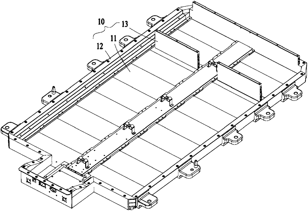
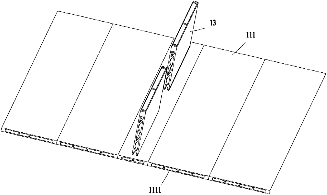
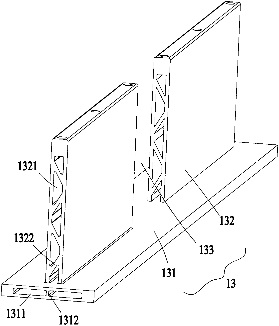
The invention discloses a battery box used for a new energy automobile. The battery box comprises a battery pack pallet and a cover body disposed on the opening of the top end of the battery pack pallet. The battery pack pallet comprises a bottom plate, a coaming, and supporting members. The coaming is extended and protruded upwards from the edge of the bottom plate, and the coaming and the bottom plate are used to form a groove used for accommodating battery components.The supporting members are disposed between the bottom plate and a cover body, and comprise a horizontally-arranged first plate body and a vertically-arranged second plate body. The second plate body is fixedly disposed on the upper part of the first plate body, and the first plate body is formed between the cover body andthe bottom plate. The second plate body is vertically disposed between the bottom plate and the cover body in a supported manner, and during the installation of the cover plate, a supporting limiting function toward the lower surface of the cover body is provided, and during the use, the pressing on the battery pack in the groove caused by the deformation of the cover body is prevented.

Description

technical field [0001] The present application relates to the technical field of new energy vehicles, in particular to a battery box for new energy vehicles and the new energy vehicles. Background technique [0002] The battery pack tray is usually formed by bending, welding or screwing metal plates. It includes a bottom plate and ribs surrounding the bottom plate. A groove with an open top is formed between the ribs and the bottom plate. The groove is used for installing battery components. , line brackets, etc. [0003] The problems existing in the existing battery trays at least include: the tray is usually formed by bending or welding metal plates, which is prone to deformation during transportation and handling, and has low strength. In order to improve its strength, the thickness of the metal plate is usually increased, and the thickness increases The weight of the entire battery pack is greatly increased, and it is difficult to meet the stringent weight requirements ...

Claims


Application Information

Patent Timeline
Patent Type & Authority Applications(China)
IPC IPC(8): H01M2/10H01M50/249
CPCH01M2220/20H01M50/20Y02E60/10
Inventor 王勤
Owner SUZHOU BRIDGE ELECTRONICS
Why Eureka
Try Eureka