Lifting mechanism in vacuum cavity

A technology of vacuum chamber and lifting mechanism, applied in crystal growth, discharge tube, electrical components, etc., can solve the problems of insufficient sealing performance, occupying chamber space, corrosion, etc., and achieve the effect of good synchronization and good dynamic sealing effect.

Pending Publication Date: 2018-08-17
常州比太黑硅科技有限公司
View PDF12 Cites 0 Cited by
  • Summary
  • Abstract
  • Description
  • Claims
  • Application Information

AI Technical Summary

Problems solved by technology

However, the existing dry texturing equipment or coating equipment has the problem of insufficient sealing performance when the lifting mechanism is used to lift the carrier plate inside the vacuum chamber; If the mechanism is placed inside the chamber, it will take up a lot of chamber space and suffer from the bombardment of the plasma in the chamber, causing serious corrosion and other problems.

Method used


Image

  • Lifting mechanism in vacuum cavity
  • Lifting mechanism in vacuum cavity
  • Lifting mechanism in vacuum cavity

Examples


Embodiment Construction

[0023] The following will clearly and completely describe the technical solutions in the embodiments of the present invention with reference to the drawings in the embodiments of the present invention.

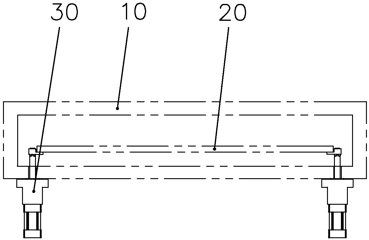
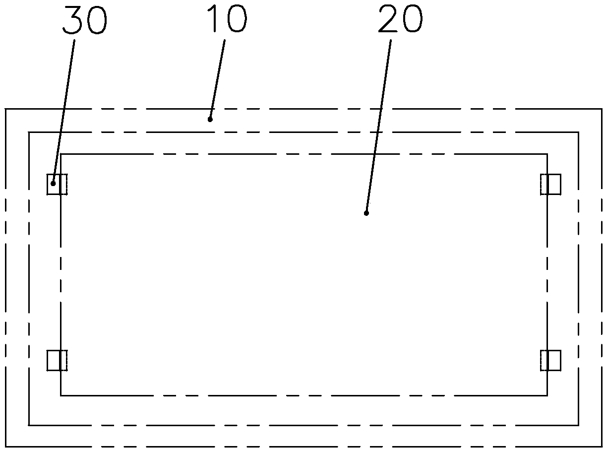
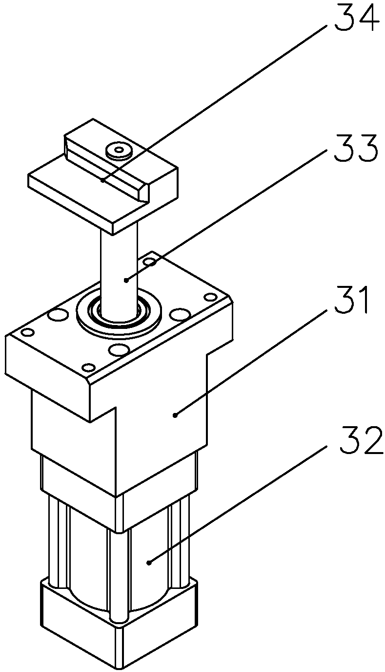
[0024] refer to Figure 1-4 , the cavity lifting mechanism 30 provided by the present invention is installed symmetrically at the four corners of the bottom of the vacuum chamber 10. The lifting mechanism 30 includes a fixed base 31 installed on the outside of the chamber bottom plate 11 of the vacuum chamber 10. The fixed base 31 is equipped with Cylinder 32, cylinder 32 drives lifting shaft 33, and one end of lifting shaft 33 stretches into vacuum chamber 10 inside through chamber bottom plate 11 and end is provided with the top plate 34 corresponding carrier plate 20; Teflon, and the outer ring of the lifting shaft 33 is processed as a high-precision sealing surface, which ensures good dynamic sealing and corrosion resistance; the inside of the fixed base 31 is provided wit...


PUM


Abstract

The invention discloses a lifting mechanism in a vacuum cavity. The lifting mechanisms are symmetrically arranged at four corners of the bottom part of the vacuum cavity, and form a good sealing environment together with sealing sleeves, O-shaped rings I, Y-shaped sealing rings, O-shaped rings II, lifting shafts and the vacuum cavity, so that the external gas is prevented from entering the vacuumcavity; an air cylinder is pushed by driving gas to act up and down, and then the lifting shafts and a top plate are driven to support a carrying plate to lift. The lifting mechanism has the advantages that the long-time good dynamic sealing effect is guaranteed under the corrosive gas environment, and the good synchronism between the lifting mechanisms is guaranteed.

Description

technical field [0001] The invention relates to the technical field of solar cell preparation, in particular to a lifting mechanism in a vacuum chamber that can be used for dry texturing equipment and aluminum oxide coating equipment. Background technique [0002] In the solar cell production process, the chamber of the battery dry texturing process or coating process requires a high temperature of 400-450 ° C, and the chamber needs to maintain this constant temperature to meet the process requirements. At the same time, the above process needs to be completed in a vacuum environment, and the vacuum degree of the chamber is 1-500Pa. Battery dry texturing or coating equipment has the characteristics of high chamber temperature and high vacuum degree, so it is very important to ensure the airtightness inside the vacuum chamber during operation. However, the existing dry texturing equipment or coating equipment has the problem of insufficient sealing performance when the lif...

Claims


Application Information

Patent Timeline
Patent Type & Authority Applications(China)
IPC IPC(8): C30B33/12H01J37/32
CPCH01J37/32513C30B33/12
Inventor 朱海剑庄正军丁建宁袁宁一上官泉元
Owner 常州比太黑硅科技有限公司
Why Eureka
Try Eureka