Denoising motor
A technology of noise reduction and motor casing, applied in the direction of electrical components, electromechanical devices, electric components, etc., to achieve stable operation, good shock and noise reduction effects
- Summary
- Abstract
- Description
- Claims
- Application Information
AI Technical Summary
Problems solved by technology
Method used
Image

Examples
Embodiment 1
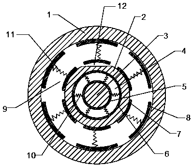
[0016] see figure 1 .
[0017] This embodiment is a noise reduction motor, including a stator 1, a rotor 2, a rotating shaft 3, a motor casing and a noise reduction group. The motor casing includes a left end cover, a right end cover and a casing. The rotating shaft 3 runs through the center of the rotor 2. The two ends of the rotating shaft 3 are respectively sleeved with a left bearing and a right bearing. The left bearing is installed in the left end cover, the right bearing is installed in the right end cover, and the left end cover is fixedly installed on the left end of the housing. The right end cover is fixedly installed on the right end of the housing, and the stator 1, the rotor 2 and the noise reduction group are all installed in the housing. The noise reduction group includes an inner noise reduction group and an outer noise reduction group. The inner noise reduction group is set between the shaft 3 and the rotor 2, the outer noise reduction group is set between ...
Embodiment 2
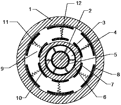
[0024] see figure 2 .
[0025] This embodiment is a noise reduction motor, including a stator 1, a rotor 2, a rotating shaft 3, a motor casing and a noise reduction group. The motor casing includes a left end cover, a right end cover and a casing. The rotating shaft 3 runs through the center of the rotor 2. The two ends of the rotating shaft 3 are respectively sleeved with a left bearing and a right bearing. The left bearing is installed in the left end cover, the right bearing is installed in the right end cover, and the left end cover is fixedly installed on the left end of the housing. The right end cover is fixedly installed on the right end of the housing, and the stator 1, the rotor 2 and the noise reduction group are all installed in the housing. The noise reduction group includes an inner noise reduction group and an outer noise reduction group. The inner noise reduction group is set between the shaft 3 and the rotor 2, the outer noise reduction group is set between...
Embodiment 3
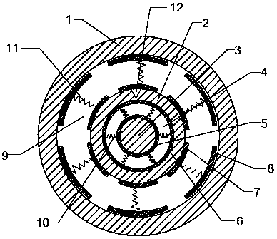
[0032] see image 3 .
[0033] This embodiment is a noise reduction motor, including a stator 1, a rotor 2, a rotating shaft 3, a motor casing and a noise reduction group. The motor casing includes a left end cover, a right end cover and a casing. The rotating shaft 3 runs through the center of the rotor 2. The two ends of the rotating shaft 3 are respectively sleeved with a left bearing and a right bearing. The left bearing is installed in the left end cover, the right bearing is installed in the right end cover, and the left end cover is fixedly installed on the left end of the housing. The right end cover is fixedly installed on the right end of the housing, and the stator 1, the rotor 2 and the noise reduction group are all installed in the housing. The noise reduction group includes an inner noise reduction group and an outer noise reduction group. The inner noise reduction group is set between the shaft 3 and the rotor 2, the outer noise reduction group is set between ...
PUM
 Abstract
Description
Claims
Application Information
 - R&D
- Intellectual Property
- Life Sciences
- Materials
- Tech Scout
- Unparalleled Data Quality
- Higher Quality Content
- 60% Fewer Hallucinations
Browse by: Latest US Patents, China's latest patents, Technical Efficacy Thesaurus, Application Domain, Technology Topic, Popular Technical Reports.
© 2025 PatSnap. All rights reserved.Legal|Privacy policy|Modern Slavery Act Transparency Statement|Sitemap|About US| Contact US: help@patsnap.com