Image forming apparatus

An image and operation panel technology, applied in image communication, short-distance communication services, instruments, etc., can solve problems such as misinputs and errors, and achieve the effect of suppressing misoperations

Inactive Publication Date: 2018-08-17
SHARP KK
View PDF10 Cites 3 Cited by
  • Summary
  • Abstract
  • Description
  • Claims
  • Application Information

AI Technical Summary

Problems solved by technology

[0004] However, since the communication area is arranged on the operation panel, when the portable terminal is brought close to the communication area, it is possible to accidentally touch the operation portion for giving instructions to the image forming apparatus and give an erroneous input.

Method used


Image

  • Image forming apparatus
  • Image forming apparatus
  • Image forming apparatus

Examples


no. 1 Embodiment approach >

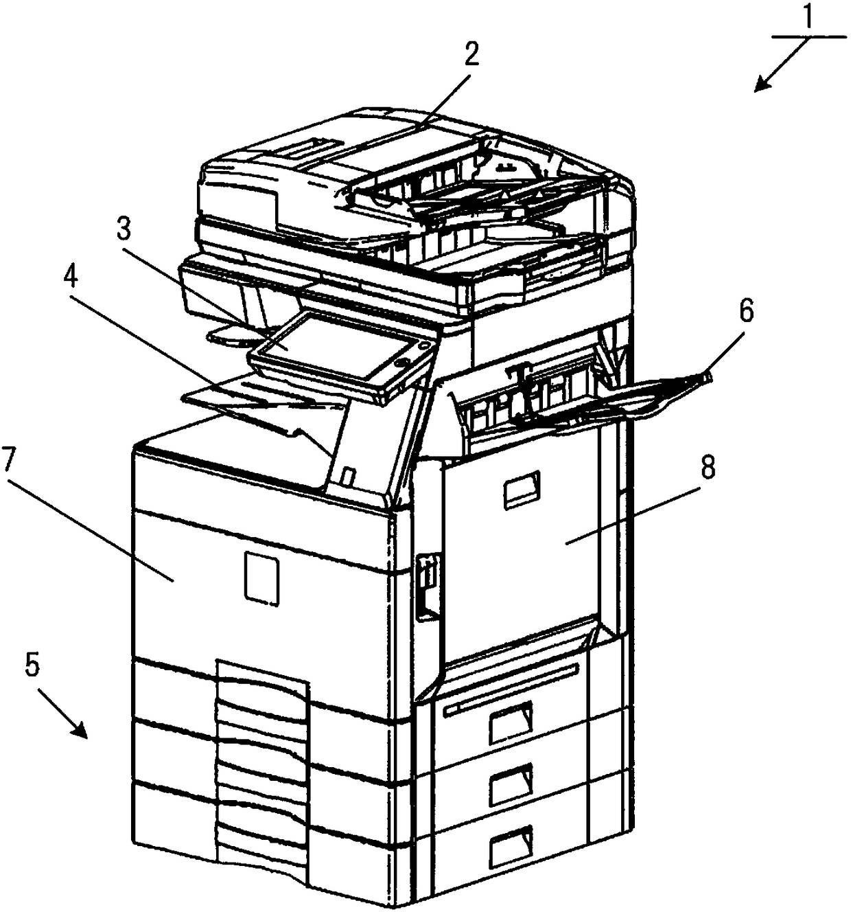
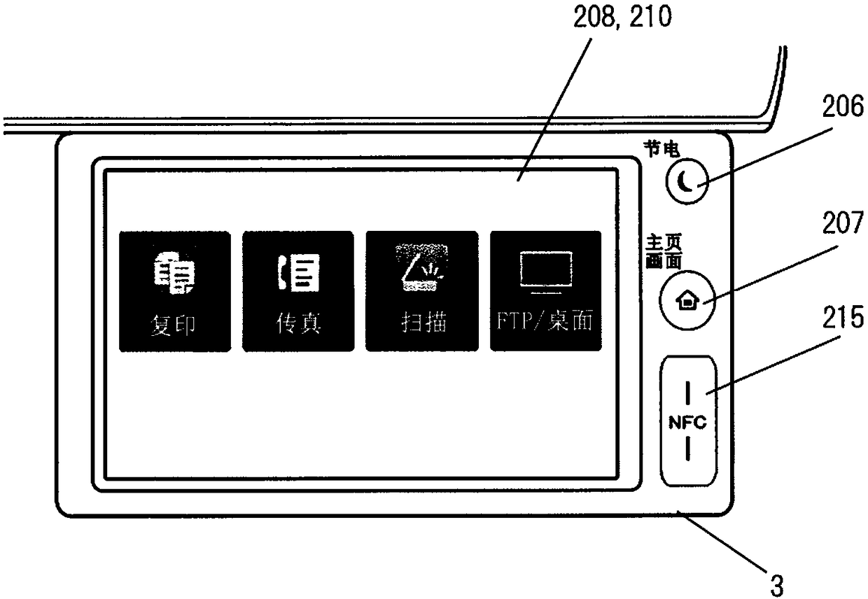
[0083] Next, the first embodiment will be described. image 3 is a diagram showing the operation panel 3 . In the figure, for the figure 1 , 2 Relevant components are denoted by the same reference numerals, and explanations thereof are omitted as necessary.

[0084] In the central part of the operation panel 3, a touch screen on which a touch panel 208 is provided on a display unit 210 is provided. image 3 In this example, four icons for selecting a copy function, a fax function, a scan function, and an FTP / desktop function are displayed on the display unit 210 . When the user touches the displayed icon, the touch position is detected by touch panel 208, and the function corresponding to the icon displayed at the position corresponding to the touch position is executed.

[0085] On the right side of the touch screen, the area for detecting the power saving key 206, the area for detecting the home key 207, and the area for detecting the home key 207 are arranged in order ...

no. 2 Embodiment approach >

[0103] Next, use Figure 7 , 8 , 9 The second embodiment will be described.

[0104] Compared with the first embodiment, it is characterized in that the communication area of ​​the NFC communication part 215 is not provided on the surface of the operation panel 3 where the power saving key 206 and the home key 207 are provided, but is provided on the surface where these keys are not provided. side of the area where interference is less likely to occur.

[0105] Figure 8 It is a perspective view showing the operation panel 3 of the second embodiment. The example of this embodiment is characterized in that an area for the NFC communication unit 215 is disposed on the side surface of the operation panel 3 . That is, the communication area of ​​the NFC communication unit 215 is provided at a position perpendicular to the area where the power saving key 206 and the home key 207 are provided. The side is located at Figure 8 Although it is arranged on the right side (the side...

no. 3 Embodiment approach >

[0112] Next, use Figure 10 , 11 , 12 The third embodiment will be described. In this embodiment, an embodiment in which an inclined portion is provided on the operation panel, and the operation area and the communication area are provided on the inclined portion with different inclination angles will be described.

[0113] In this embodiment, the area for the NFC communication unit 215 is provided on the surface of the operation panel 3 similarly to the first embodiment, but the difference is that this area is provided with an inclination.

[0114] As an example, an example of this embodiment is characterized in that the communication area of ​​the NFC communication unit 215 is provided on the near side from the vertex of the slope, and the height gradually increases from the front side of the operation panel 3 to the far side (near the center), and In addition, the operation areas of the power saving key 206 and the home key 207 are provided in an area that gradually becom...


PUM


Abstract

An image forming apparatus, includes: a short-range wireless communication unit that performs wireless communication with a mobile terminal that is in proximity; an operating portion that receives operational instructions from a user; and an operation panel having a communication area of the short-range wireless communication unit and an operation area of the operating portion on the same surface.The operation panel is constructed such that the communication area of the short-range wireless communication unit is arranged around a corner portion on the near side of the operation area where theoperating portion of the operation panel is arranged, as viewed from the user side who operates the operation panel.

Description

technical field [0001] The present invention relates to an image forming apparatus having a short-range wireless communication function capable of performing near-field wireless communication with a portable terminal. Background technique [0002] In recent years, as a method of importing image data stored in an external portable terminal into an image forming device, an image forming device that uses simple wireless communication instead of the conventional method of using a memory card to import image data has been proposed. In particular, a design has been adopted in which NFC (Near Field Communication) with a slow communication speed is used as a trigger for transmitting image data, and the image data itself is transmitted by communication using preset WiFi (registered trademark) communication. Import image data from a portable terminal. [0003] At this time, it is necessary to make the portable terminal equipped with NFC and the image forming apparatus close to a shor...

Claims


Application Information

Patent Timeline
Patent Type & Authority Applications(China)
IPC IPC(8): H04N1/00H04W4/80G06F1/16
CPCH04N1/00496H04N1/00307H04N1/00315H04N1/00411H04N1/00493H04N1/00559H04N1/32683H04N2201/006H04N2201/0063H04N2201/0094H04N1/00127G06F1/1698H04W4/80
Inventor 井户爱井上康弘加集阳介川野雅央小西利幸
Owner SHARP KK
Why Eureka
Try Eureka