Electric motor with a position detector

A technology of detectors and motors, applied in the field of motors, can solve the problems of no effect of electromagnetic interference, improve anti-interference, and difficulty in simultaneously suppressing thermal movement to the position detector

Inactive Publication Date: 2010-03-03
PANASONIC CORP
View PDF3 Cites 2 Cited by
  • Summary
  • Abstract
  • Description
  • Claims
  • Application Information

AI Technical Summary

Problems solved by technology

[0013] However, in the conventional detector cover, it is difficult to achieve both the suppression of heat transfer to the position detector and the improvement of noise immunity.
[0014] In the technology of Patent Document 1, since the resin molding shaft and the rotating shaft are separately formed, heat transfer to the position detector can be suppressed, but there are problems in connection accuracy and position accuracy after connection
In addition, it has no effect on electromagnetic interference
[0015] In addition, in the technique of Patent Document 2, since the space between the protective wall of the encoder cover and the rotary encoder is filled with a resin composition, although heat transfer to the position detector can be suppressed, the management of the gap and filling amount issues
In addition, as in Patent Document 1, it has no effect on electromagnetic interference
[0016] On the other hand, the technique of Patent Document 3 is effective for electromagnetic shielding (anti-interference), but in terms of thermal countermeasures, heat radiation is promoted in the detector cover, so it has an opposite effect.
[0017] Thus, in these prior art, it is difficult to simultaneously suppress thermal transfer to the position detector and improve noise immunity.

Method used


Image

  • Electric motor with a position detector
  • Electric motor with a position detector
  • Electric motor with a position detector

Examples


Embodiment approach 1

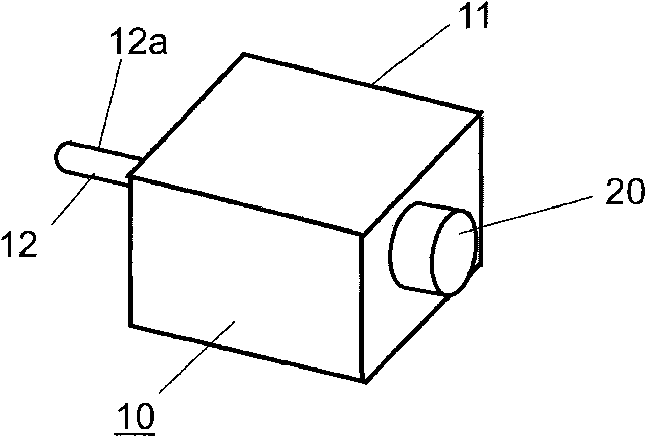
[0025] figure 1 It is an external view of a motor with a position detector according to Embodiment 1 of the present invention. like figure 1 As shown, a motor 10 , which is a motor with a position detector, has a rotating shaft 12 for rotationally driving a load extending from a motor main body 11 . figure 1 In the diagram, the output shaft 12a on the output shaft side for the drive output is extended with respect to the rotating shaft 12 . In addition, a position detection unit 20 having an appearance of a substantially cylindrical shape is arranged on the opposite side to the output shaft side, that is, on the opposite side to the output shaft.

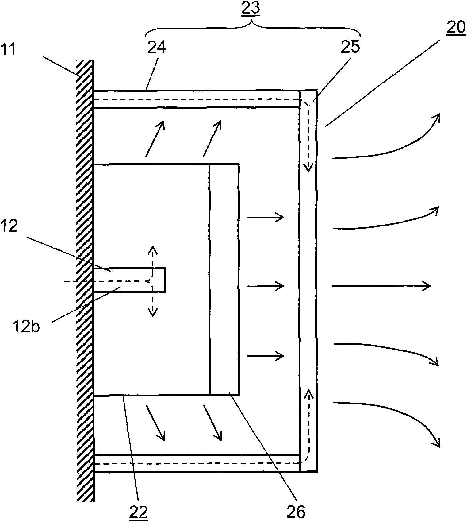
[0026] figure 2 It is a cross-sectional view of the main part of the position detection unit 20 of the motor 10 according to Embodiment 1 of the present invention. figure 2 The center represents the side opposite to the output shaft 12 b extending from the motor main body 11 on the opposite side of the rotating shaft 12 .

[...

Embodiment approach 2

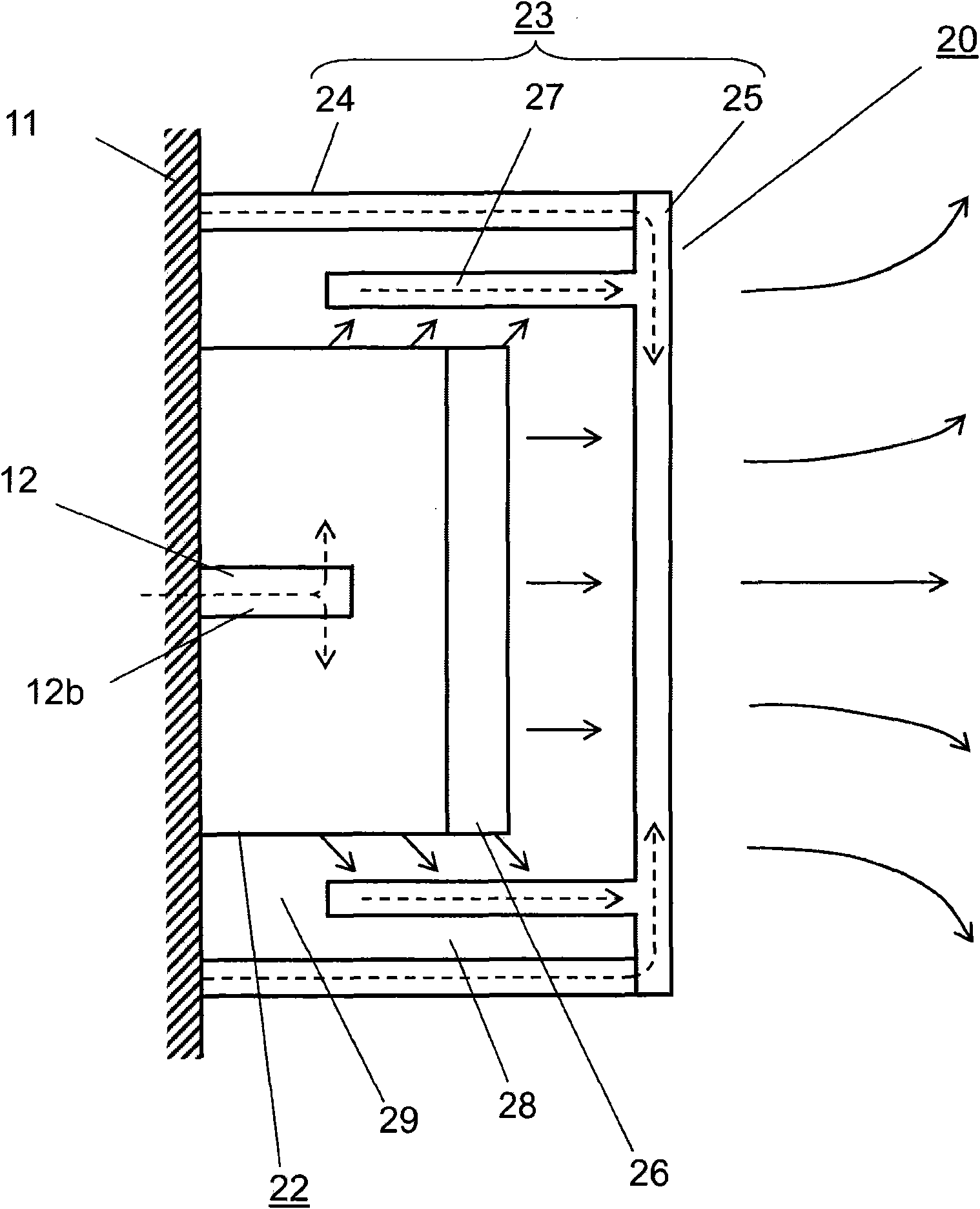
[0038] image 3 It is a cross-sectional view of the main part of the position detection unit 20 of the motor 10 according to Embodiment 2 of the present invention. image 3 In the figure, the side opposite to the output shaft where the output shaft 12 b extends from the motor main body 11 is also shown. Additionally, with figure 2 The same components are denoted by the same symbols, and detailed descriptions are omitted. In comparison with Embodiment 1, the detector cover 23 of the motor 10 of this embodiment further includes a cylindrical wall portion 27 .

[0039] The cylindrical wall portion 27 has a hollow cylindrical shape and is integrally formed with the metal bottom portion 25 . The cylinder wall portion 27 is disposed on the inner peripheral side of the cylinder portion 24 , parallel to the cylinder portion 24 with a gap 28 therebetween, and extends from the bottom portion 25 toward the position detection unit 20 . That is, by installing the detector cover 23 in ...


PUM


Abstract

The present invention relates to an electric motor with a position detector, which has a position detector mounted at one side opposite to an output shaft of the electic motor and a detector cover forcovering the position detector, wherein the detector cover comprises a barrel portion made of synthetic resin and a bottom made of metal. In addition, the detector cover also comprises a barral wallportion which is integrally formed with the bottom and arranged at the inner periphery of the barrel portion.

Description

technical field [0001] The present invention relates to a motor equipped with a position detector, that is, a motor with a position detector, and more particularly, to a motor with a position detector in which temperature rise of the position detector is suppressed (thermal countermeasures) and noise resistance is improved. Background technique [0002] In recent years, miniaturization and high positioning accuracy are being sought for servo motors that drive FA equipment. [0003] Rotary encoders and resolvers are usually used as position detectors to control the positioning accuracy of servo motors, and they are used separately according to the application. Among these position detectors, optical rotary encoders have higher positioning accuracy than resolvers, but have problems in heat resistance and electromagnetic interference resistance. [0004] A position detector such as a rotary encoder requires a signal processing circuit that includes circuit parts that are poor ...

Claims


Application Information

Patent Timeline
Patent Type & Authority Applications(China)
IPC IPC(8): H02K11/00H02K5/04H02K5/02H02K29/10
Inventor 田村真也佐藤和男清水英二森冈正之吉良嘉洋
Owner PANASONIC CORP
Why Eureka
Try Eureka