Power recovery circuit, plasma display, module for plasma display

A plasma display and power recovery technology, applied to static indicators, instruments, identification devices, etc., can solve problems such as excessive temperature rise and damage, and achieve the effect of suppressing misoperation

Inactive Publication Date: 2006-06-21
SANYO ELECTRIC CO LTD
View PDF1 Cites 2 Cited by
  • Summary
  • Abstract
  • Description
  • Claims
  • Application Information

AI Technical Summary

Problems solved by technology

This malfunction may cause the temperature of Q4 to rise excessively and cause damage

Method used


Image

  • Power recovery circuit, plasma display, module for plasma display
  • Power recovery circuit, plasma display, module for plasma display
  • Power recovery circuit, plasma display, module for plasma display

Examples


Embodiment Construction

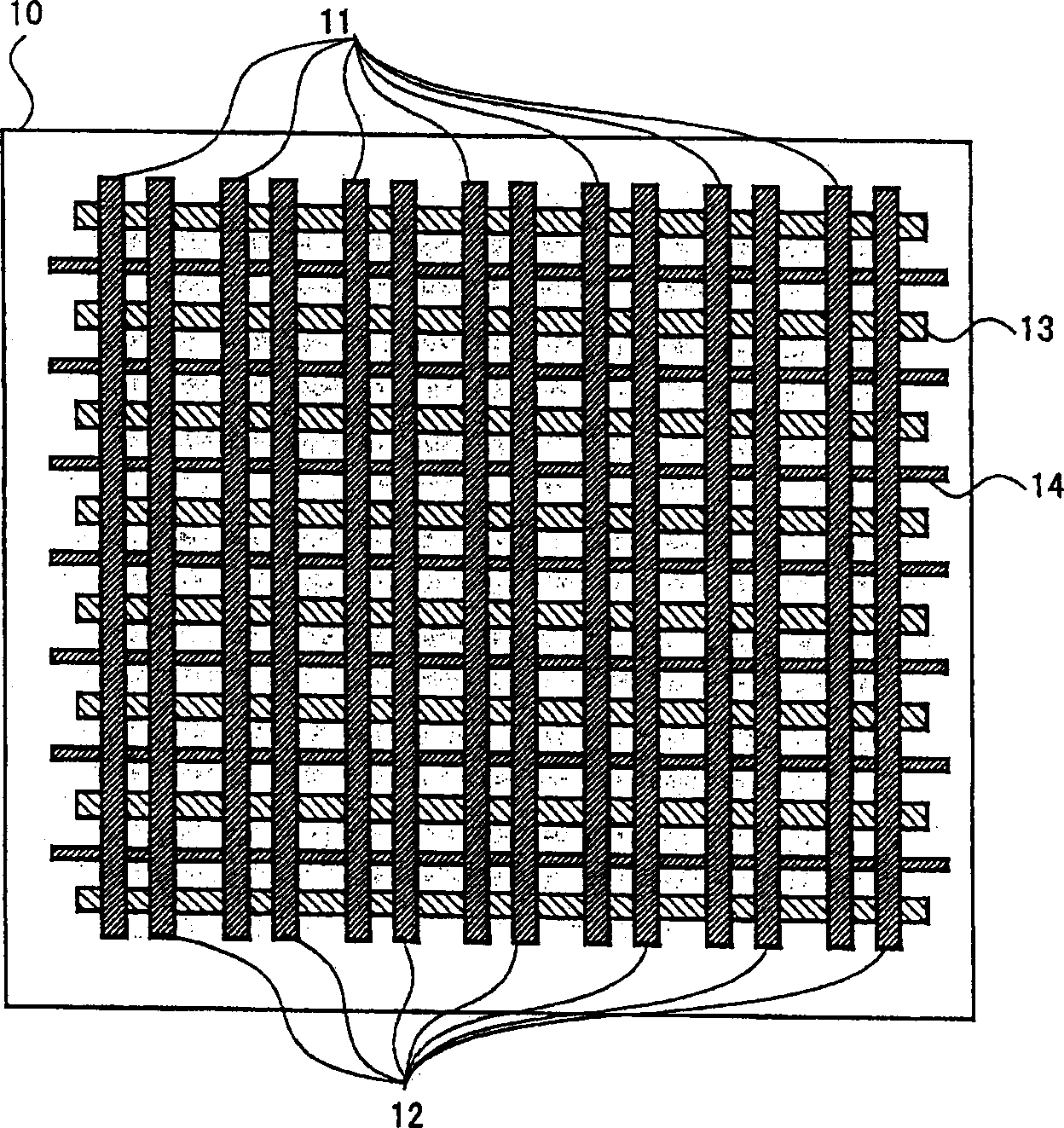
[0062] figure 1 It is a plan view showing the outline of plasma display panel 10 . X electrodes 11 and Y electrodes 12 arranged in parallel are formed on display panel 10 , and address electrodes 14 are formed perpendicular to these. The X electrode 11 and the Y electrode 12 are electrodes that mainly perform sustain discharge for light-emitting display. Sustain discharge is performed by repeatedly applying a voltage pulse between the X electrode 11 and the Y electrode 12 . On the other hand, address electrode 14 is an electrode for selecting a discharge cell to emit light, and a voltage for performing address discharge for selecting a discharge cell is applied between Y electrode 12 and address electrode 14 . A spacer 13 is formed between the address electrodes 14 to separate the discharge cells.

[0063] Since the discharge of the plasma display has only two values ​​of on or off, the brightness is expressed by the number of times of light emission. That is, the number ...


PUM


Abstract

A power recovery circuit and a plasma display for suppressing misoperation of switching elements. It has, a capacitor (C2) that accumulates electric power recovered from the panel (C1), a third switching element (Q3) that discharges the capacitor (C2), and a fourth switching element (Q4) that charges the capacitor (C2) a level shifter (28) shifting the control signal of the control (Q4) to the voltage level of the capacitor (C2), the threshold voltage of (Q4) being higher than the threshold voltage of (Q3). Therefore, it is possible to prevent the malfunction of (Q4) caused by the voltage drop of capacitor (C2).

Description

technical field [0001] The present invention relates to a power recovery circuit, a plasma display, and a module for a plasma display, and more particularly, to a power recovery circuit, a plasma display, and a module for a plasma display that prevent malfunction of switching elements constituting the power recovery circuit. Background technique [0002] The plasma display panel (hereinafter referred to as PDP) has a thin structure, no flicker, and a large display contrast. In addition, the PDP can be formed into a larger screen with a fast response speed. It is self-illuminating, and it can also use phosphors for multicolor emission . Therefore, in recent years, it has been widely used in the field of computer-related display devices, the field of color image display, and the like. [0003] In the PDP, a drive circuit for supplying a voltage to a panel as a capacitive load is required. In addition, a power recovery circuit for recovering power from a panel is also used (s...

Claims


Application Information

Patent Timeline
Patent Type & Authority Applications(China)
IPC IPC(8): G09G3/291G09F9/313G09G3/20G09G3/296H01J17/49
CPCG09G3/2965G09G2330/04G09G3/296
Inventor 久保田裕冈崎纪生新井一正
Owner SANYO ELECTRIC CO LTD
Why Eureka
Try Eureka