
Power Eccentric Chuck

An eccentric clamping, power technology, applied in clamping, manufacturing tools, metal processing machinery parts, etc., can solve the problems of reduced processing efficiency, slow processing, inefficiency, etc.

Active Publication Date: 2020-11-17
上海瑞麒美贸易有限公司 +1
View PDF5 Cites 0 Cited by
  • Summary
  • Abstract
  • Description
  • Claims
  • Application Information

AI Technical Summary

Problems solved by technology

[0002] Generally, if the workpiece needs to be processed eccentrically, it is mainly to clamp the workpiece in the chuck of the machine tool in a way that deviates from the axis of the rotating spindle of the machine tool. This clamping method requires manual and gradual adjustment of the position of each jaw of the chuck. Then use the jaws to fix the workpiece to be processed, the whole processing is slow and inefficient
[0003] Moreover, in the above-mentioned eccentric machining, in order to avoid the vibration of the rotating main shaft during rotation, resulting in a decrease in machining accuracy or damage to the machine tool equipment, the rotating main shaft is usually rotated at a low speed, which also reduces the processing efficiency.
Furthermore, when the rotating spindle is subjected to a bias load, the rotation is also likely to shorten the service life

Method used


Image

  • Power Eccentric Chuck
  • Power Eccentric Chuck
  • Power Eccentric Chuck

Examples


Embodiment Construction

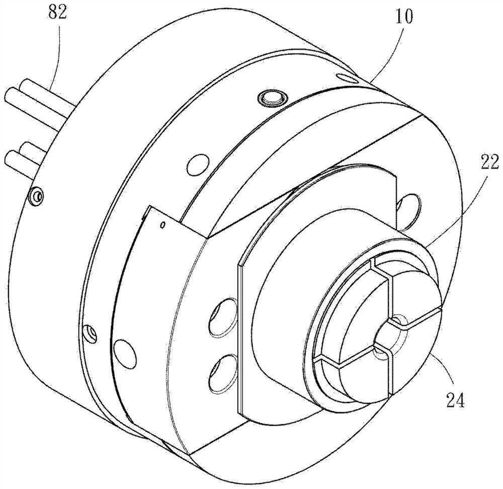
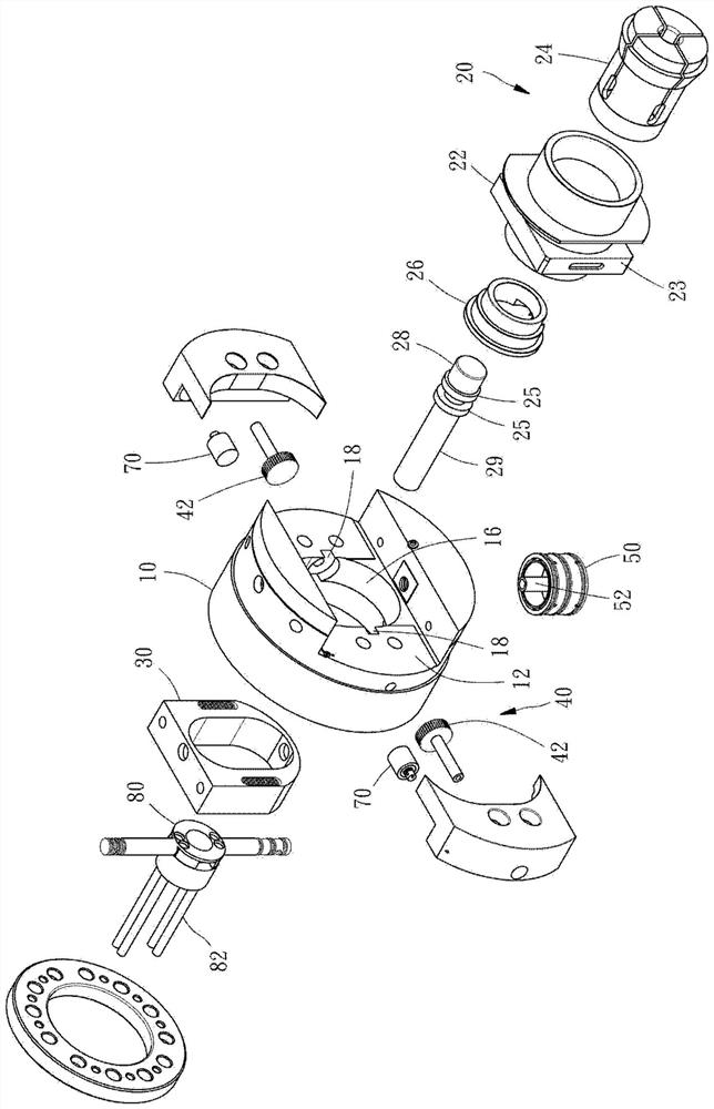
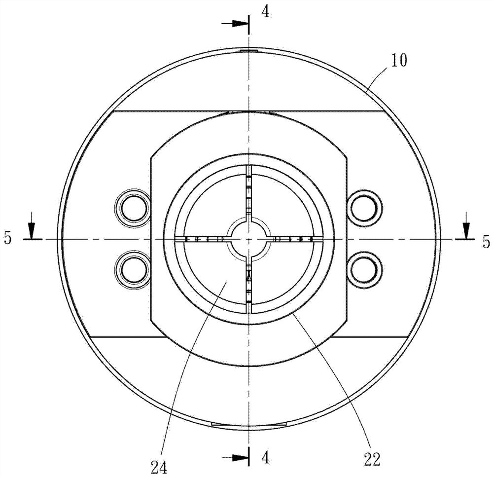
[0043] see Figure 1 to Figure 5 As shown, the dynamic eccentric chuck provided by a preferred embodiment of the present invention includes a main body 10 , a clamping device 20 , a counterweight 30 and a transmission mechanism 40 . The main body 10 has a substantially cylindrical shape and is mounted on a rotating spindle of a machine tool. The main body 10 has a front chute 12, a rear chute 14 and a central hole 16 connecting the front and rear chute 12, 14. Two chambers 18 are arranged on the peripheral wall of the main body 10, and the two chambers 18 are symmetrically located on the main body 10. on both sides. The transmission mechanism 40 includes two gear shafts 42 , and each gear shaft 42 is rotatably disposed inside each chamber 18 , and part of the teeth of the gear shafts 42 are respectively exposed to the front and rear chute 12 , 14 . The bottom side of the main body 10 is also provided with an oil pressure cylinder 50 , and the oil pressure cylinder 50 has a p...


PUM


Abstract

The invention provides a power-type eccentric chuck. The power-type eccentric chuck is provided with a clamping device which can move in the axial direction of a rotating main shaft and is used for clamping a workpiece and at least one balance weight parts, and the power-type eccentric chuck is further provided with a transmission mechanism which is used for driving the clamping device to eccentrically move and synchronously drive the balance weight parts to move in the reverse direction. The power-type eccentric chuck not only can clamp the workpiece to eccentrically rotate in a power drivingmode, but also can maintain the gravity center, and the condition that eccentric vibration is generated when the chuck rotates at high speed is avoided.

Description

technical field [0001] The invention relates to a machining device, in particular to a dynamic eccentric chuck of the machining device. Background technique [0002] If the general workpiece needs to be processed eccentrically, it is mainly to clamp the workpiece in the chuck of the machine tool in a way that deviates from the axis of the rotating spindle of the machine tool. This clamping method requires manual and gradual adjustment of the position of each jaw of the chuck. Then use the jaws to fix the workpiece to be processed, the whole processing is slow and inefficient. [0003] Moreover, during the above-mentioned eccentric machining, in order to avoid the reduction of machining accuracy or the damage of the machine tool due to the vibration of the rotating main shaft during rotation, the rotating main shaft is usually rotated at a low speed, which also reduces the processing efficiency. Furthermore, when the rotating main shaft is subjected to a bias load, the rotat...

Claims


Application Information

Patent Timeline
Patent Type & Authority Patents(China)
IPC IPC(8): B23Q3/12
CPCB23Q3/12
Inventor 吴亚爵
Owner 上海瑞麒美贸易有限公司
Learn More