Land leveler, tray type working device thereof and traction frame and rotary frame connecting device

A technology of connecting device and working device, which is applied to mechanically driven excavators/dredgers, etc., can solve the problems of difficulty in adjusting the radial clearance and axial clearance of the slewing frame, the blade and the traction frame, and achieve simple structure, clearance Simple, low-cost effects to adjust

Pending Publication Date: 2018-08-21
SHANDONG LINGONG CONSTR MACHINERY
View PDF0 Cites 0 Cited by
  • Summary
  • Abstract
  • Description
  • Claims
  • Application Information

AI Technical Summary

Problems solved by technology

[0004] In order to solve the shortcomings of the traditional pallet-type working device in the prior art, which are difficult to adjust the radial clearance and axial clearance between the slewing frame and the blade and the traction frame, the present invention provides a motor grader and its pallet that are different from the prior art Type working device and connecting device between traction frame and slewing frame, its adjustment method and structure are simple, and the cost is low

Method used


Image

  • Land leveler, tray type working device thereof and traction frame and rotary frame connecting device
  • Land leveler, tray type working device thereof and traction frame and rotary frame connecting device
  • Land leveler, tray type working device thereof and traction frame and rotary frame connecting device

Examples


Embodiment 1

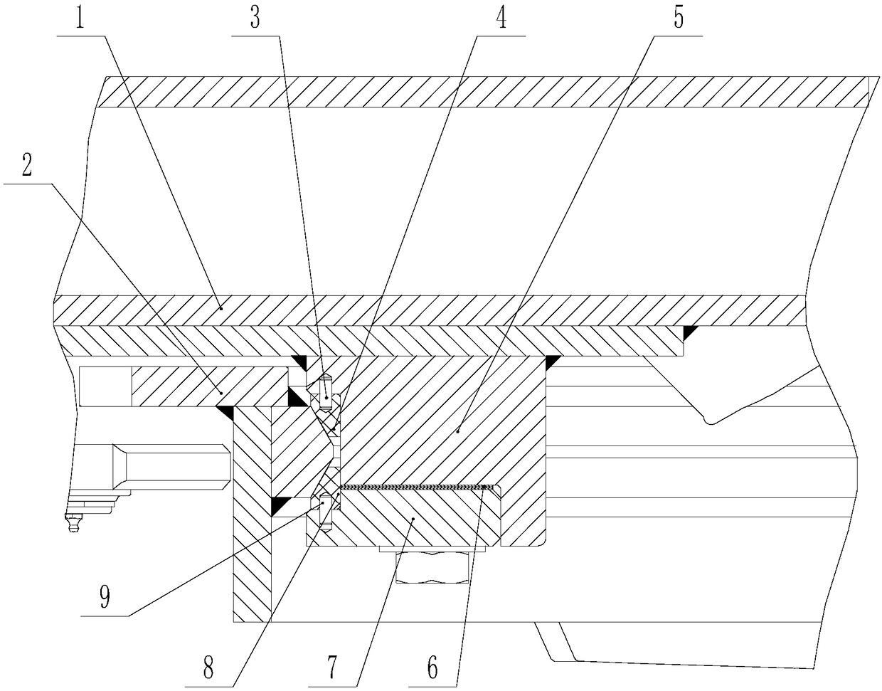
[0028] Such as Figure 1-3 As shown, a connection device between the traction frame and the slewing frame includes an upper guide plate 5, a lower guide plate 7, an upper wear plate 4 and a lower wear plate 8, the upper wear plate 4 is connected with the upper guide plate 5, The lower guide plate 7 is connected with the lower wear plate 8, the upper guide plate 5 is connected with the lower guide plate 7 and an adjusting gasket 6 is arranged between the upper guide plate 5 and the lower guide plate 7; the upper wear plate 4 The upper guide plate 5 is connected with the positioning pin I3 and the screw I11, and the lower wear plate 8 is connected with the lower guide plate 7 through the positioning pin II9 and the screw II12.

Embodiment 2

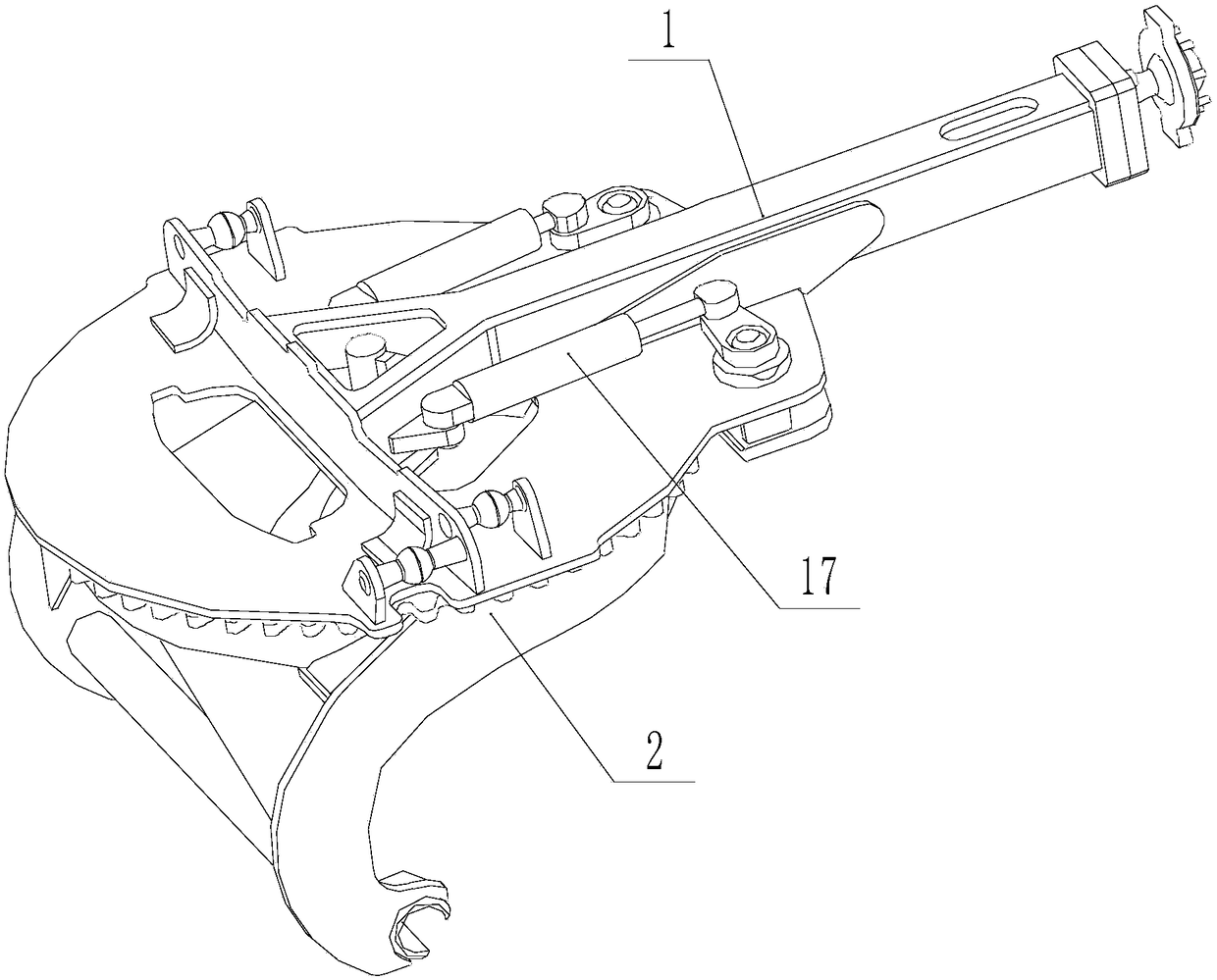
[0030] A pallet-type working device, comprising a traction frame 1, a rotary frame 2 and a rotary drive mechanism 17, the above-mentioned traction frame and rotary frame connecting device is arranged between the traction frame 1 and the rotary frame 2; the rotary frame 2 is arranged on the traction Between the frame 1 and the lower guide plate 7, the upper wear-resistant plate 4 and the lower wear-resistant plate 8 are arranged between the rotary frame 2 and the upper guide plate 5 and the lower guide plate 7; the rotary drive mechanism 17 drives the rotary frame 2 to realize the The relative rotary motion of the traction frame 1.

Embodiment 3

[0032] Such as Figure 3-5 As shown, a pallet-type working device, the upper guide plate 5 is welded on the traction frame 1, and the lower guide plate 7 is assembled and connected with the upper guide plate 5 through the bolt I10 and the adjusting gasket 6. Other parts are identical with embodiment 2.

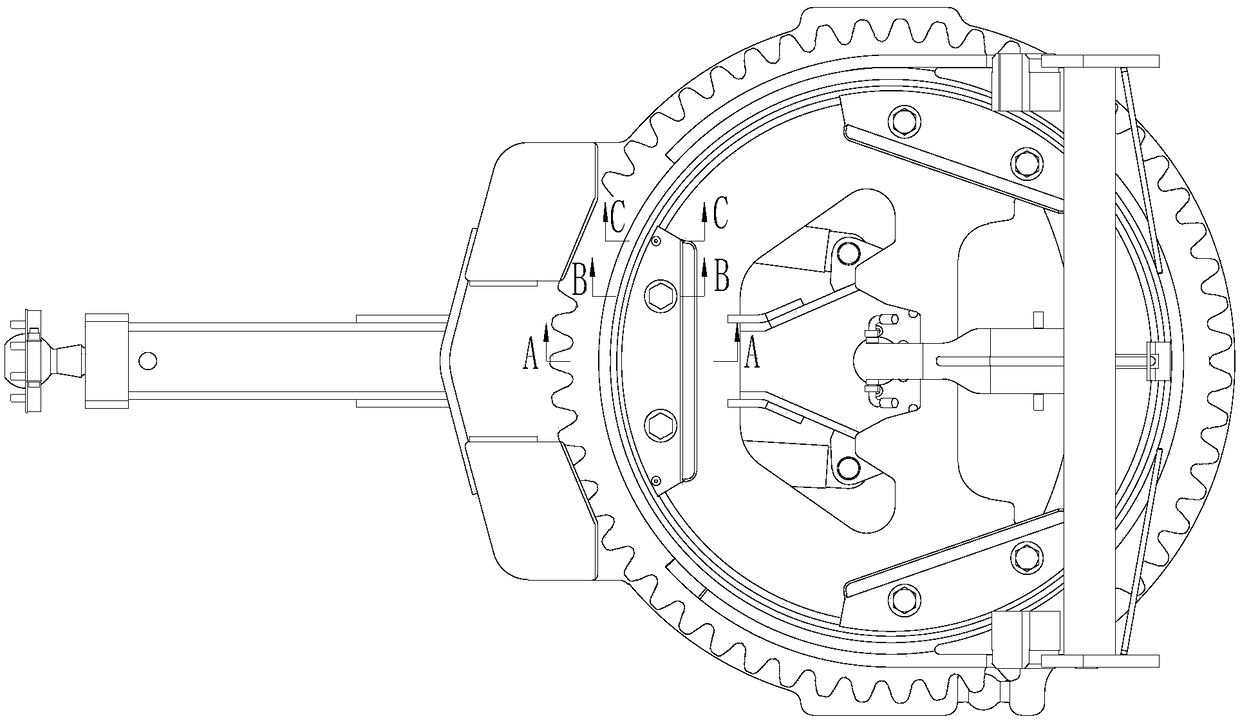
[0033] Such as Figure 6 As shown, the traction frame 1 is provided with three or more upper guide plates 5, and the lower guide plate 7 is processed with several pin holes 20 for positioning, screw holes 21 for positioning and bolt holes 19 for fixed connection with the upper guide plate 5. .

[0034] In this embodiment, when installing, the lower guide plate 7 passes through the upper guide plate 5 to assemble the bolt I10. When in use, according to the requirements of the working conditions, the rotary drive mechanism 17 drives the upper and lower sliding surfaces of the inner ring of the rotary frame 2 and the upper wear plate 4 and The lower wear plate 8 relatively sli...


PUM


Abstract

The invention discloses a land leveler, a tray type working device thereof and a traction frame and rotary frame connecting device and belongs to the technical field of engineering machinery. Throughthe tray type working device thereof and the traction frame and rotary frame connecting device, the problems that in a traditional tray type working device in the prior art, the radial clearance and the axial clearance of a rotary frame, a shovel blade and a traction frame are difficult to adjust. A main structure of the traction frame and rotary frame connecting device comprises an upper guide plate, a lower guide plate, an upper wear-resisting plate and a lower wear-resisting plate. The upper wear-resisting plate is connected with the upper guide plate. The lower guide plate is connected with the lower wear-resisting plate. The upper guide plate is connected with the lower guide plate. An adjusting gasket is arranged between the upper guide plate and the lower guide plate. The traction frame and rotary frame connecting device is mainly applied to the land leveler.

Description

Technical field: [0001] The invention belongs to the technical field of engineering machinery, and in particular relates to a motor grader, a tray-type working device thereof, and a connection device between a traction frame and a slewing frame. Background technique: [0002] The grader realizes various tasks such as leveling roads and farmland, scraping side slopes, and scraping inclined ditches through the blade working device. During work, it is necessary to drive the slewing frame and the blade to rotate through the slewing drive mechanism, so as to realize the adjustment of the rotation angle of the blade to meet the needs of various working conditions. At present, there are two connection methods for the rotary frame of the motor grader, the blade and the traction frame: one is the tray-type working device, and the rotary frame is connected to the traction frame through a guide plate, a pressure plate, etc. It is necessary to adjust the axial clearance and radial clea...

Claims


Application Information

Patent Timeline
IPC IPC(8): E02F3/80
CPCE02F3/80
Inventor 苗国华王永崔元福冯克祥王桂印李勇赵旭光
Owner SHANDONG LINGONG CONSTR MACHINERY
Why Eureka
Try Eureka