Extrusion mould head for plastic tube

A technology for extruding dies and plastic pipes, which is applied in the direction of tubular objects, other household utensils, household utensils, etc. It can solve the problems of cumbersome adjustment steps of plastic pipe extrusion dies, material leakage, plastic accumulation and burnt materials, etc., to achieve The effect of preventing the leakage of the die head and the simple adjustment process of the gap

Active Publication Date: 2010-06-23
NINGBO FANGLI GRP
View PDF5 Cites 0 Cited by
  • Summary
  • Abstract
  • Description
  • Claims
  • Application Information

AI Technical Summary

Problems solved by technology

[0004] 1. When adjusting the gap between the outer wall of the mandrel and the inner wall of the die, since the die is pressed tightly on the adjustment seat by the pressure plate, it is difficult to move the die directly by adjusting the adjustment screw in the radial direction, and the operator needs to properly Loosen the compression screw on the pressure plate, and then adjust the adjustment screw in the radial direction, so that the die moves radially in the direction of the adjustment screw, so as to realize the adjustment of the gap between the outer wall of the core die and the inner wall of the die, and the adjustment is completed Finally, tighten the compression screw to ensure that the contact surface is flat. From the above adjustment process, it is not difficult to find that the adjustment steps of the prior art plastic pipe extrusion die seem more loaded down with trivial details;
[0005] 2. When the pipe is being extruded, due to the large pressure in the outlet section of the raw material channel, when the compression screw is properly loosened, under the action of pressure, the right end surface of the mandrel and the adjustment seat A small gap will appear on the left end surface, causing part of the plastic to leak out through this small gap, resulting in material leakage.
[0006] 3. Since the contact area between the right end face of the mandrel and the left end face of the adjustment seat is not very large, after adjusting the gap between the outer wall of the mandrel and the inner wall of the mouth die, there may be misalignment between the right end face of the mandrel and the left end face of the adjustment seat and form two large crescent-shaped steps, which not only hinder the flow of plastic in the die, but also form the phenomenon of plastic accumulation and coke

Method used


Image

  • Extrusion mould head for plastic tube
  • Extrusion mould head for plastic tube
  • Extrusion mould head for plastic tube

Examples


Embodiment Construction

[0020] The present invention will be further described below in conjunction with accompanying drawing and specific embodiment:

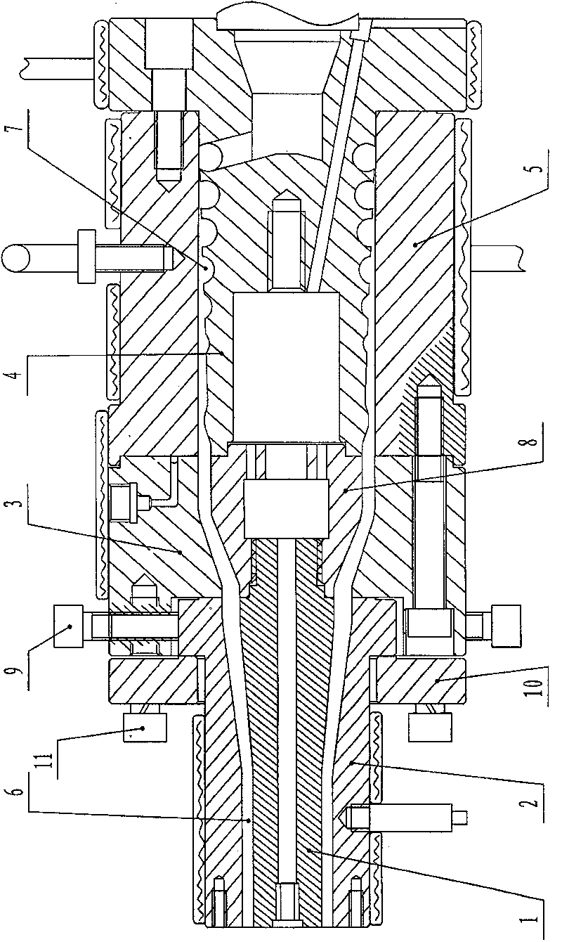
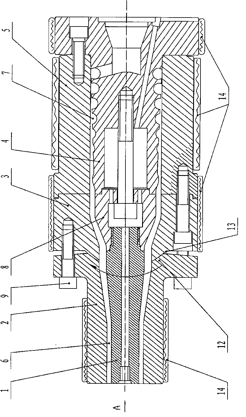
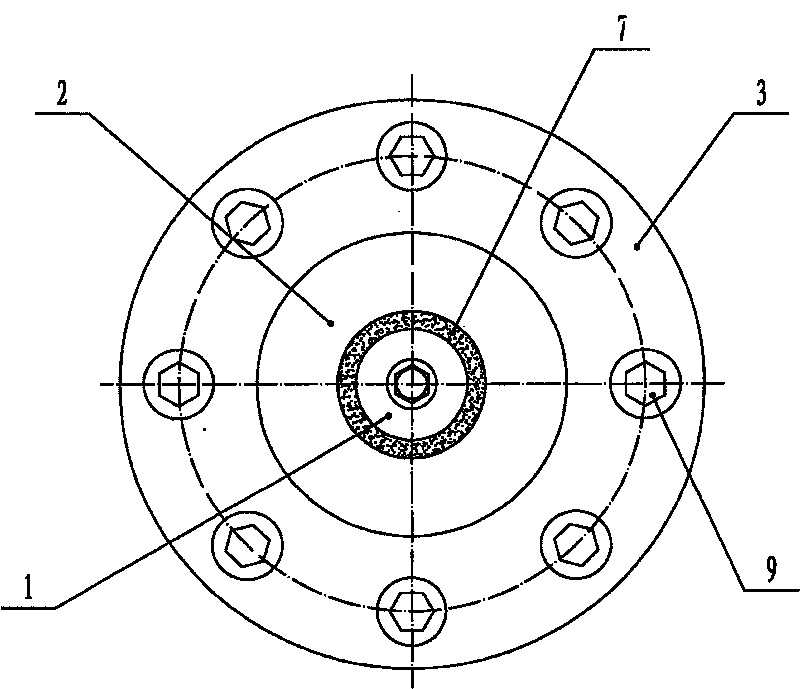
[0021] Such as figure 2 As shown, in this specific embodiment, the plastic pipe extrusion die head of the present invention includes a mandrel 1, a die 2, a core rear body 4, an outer mold rear body 5, and adjusting screws 9 whose number is a multiple of four. The said number of adjusting screws 9 being a multiple of four means that the number of adjusting screws 9 may be four, eight or sixteen. In this specific embodiment, the number of said screws 9 is eight. In this specific embodiment, between the outer wall of the core mold 1 and the inner wall of the die 2 is the outlet section 6 of the raw material channel; between the outer wall of the mold core 4 and the inner wall of the rear body 5 of the outer mold is the inlet section 7 of the material channel; The outlet section 6 of the raw material channel is connected to the inlet section 7 of the ...


PUM


Abstract

The invention discloses a plastic pipe extrusion die head, comprising a core die (1) fixed on a die core rear body (4), a die (2) the left end face of which is parallel to the left end face of the core die (1), an adjusting seat (3), an outer die rear body (5) the right end of which is fixed with the right end of the die core rear body (4) and adjusting screws (9) the number of which is multiple of four, wherein, the die (2) is connected with the adjusting seat (3) through the adjusting screws (9) which are uniformly distributed on the die and axes of which are parallel to the axis of the diehead; the center of the right end of the die (2) is a concave spherical surface I(12); the center of the right end of the adjusting seat (3) is a convex spherical surface II(13); and the concave spherical surface I(12) and the convex spherical surface II(13)are mutually attached. The plastic pipe extrusion die head has the advantages that: the plastic pipe extrusion die head not only can simply adjust a gap of a straight section between a core die outer wall and a die inner wall, but also can make plastics flow smoothly in the die head in the adjusting process, without accumulation, coke charge and leakage.

Description

Technical field: [0001] The invention relates to an extrusion die head, in particular to a plastic pipe extrusion die head capable of adjusting the wall thickness of the pipe material to make it uniform. Background technique: [0002] Prior art plastic pipe extrusion die head, as figure 1 As shown, it generally includes a mandrel 1, a die 2, a core rear body 4 and an outer mold rear body 5; between the outer wall of the mandrel 1 and the inner wall of the die 2 is the outlet section 6 of the raw material channel; the core 4 Between the outer wall and the inner wall of the rear body 5 of the outer mold is the material channel inlet section 7; the material channel outlet section 6 is connected to the material channel inlet section 7; the right end of the core mold 1 is threaded on the core mold base 8 Above; the mandrel base 8 is fixed on the mold core rear body 4 by screws; the right end of the mold core rear body 4 is fixed on the right end of the outer mold rear body 5 by ...

Claims


Application Information

Patent Timeline
Patent Type & Authority Patents(China)
IPC IPC(8): B29C47/22B29L23/00B29C48/325
Inventor 王尚锋
Owner NINGBO FANGLI GRP
Why Eureka
Try Eureka