
Solar rubbish compression box
A technology of garbage compression and solar energy, which is applied in the direction of garbage cans, garbage collection, waste collection and transfer, etc., can solve the problems of unfavorable saving and dependence on external power supply, and achieve the effects of easy use and operation, energy saving and full use of light energy
- Summary
- Abstract
- Description
- Claims
- Application Information
AI Technical Summary
Problems solved by technology
Method used
Image

Examples
no. 1 example
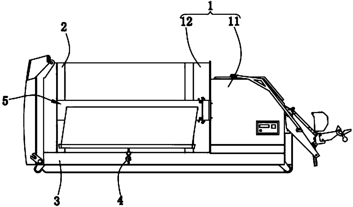
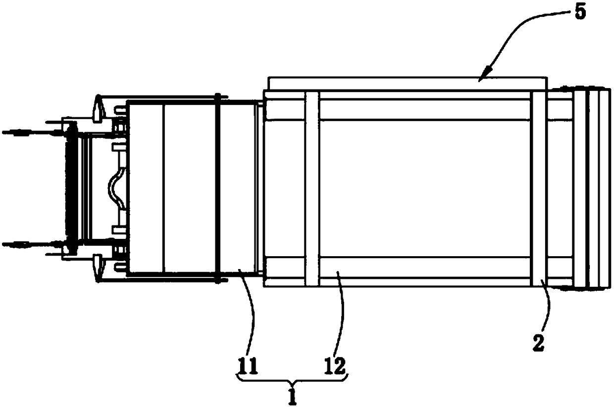
[0055] Please refer to Figure 1-5 , in the first embodiment of the present invention, the solar garbage compactor includes:
[0056] Box 1;
[0057] The transmission device 2, the transmission device 2 is arranged in the box body 1;
[0058] The accumulator assembly 5, the accumulator paper assembly is arranged on the conveying device 2;
[0059] A driving device 3, the driving device 3 is used to drive the storage battery assembly 5 to move along the extending direction of the conveying device 2;
[0060] The first connecting piece 4, the first connecting piece 4 is arranged on the box body 1;
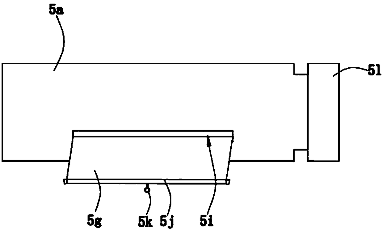
[0061] The accumulator assembly 5 includes:
[0062] A casing 5a, the casing 5a is arranged on the conveying device 2, and an opening 5i is formed on the casing 5a;
[0063] The slider 5b is formed by bending and extending from one end of the housing 5a;
[0064] The rotating shaft 5d, the rotating shaft 5d is arranged in the casing 5a;
[0065] The bump 5e is formed by protru...
no. 2 example
[0090] see Figure 6-7 , based on the solar garbage compression box provided in the first embodiment, the difference of the solar garbage compression box provided in this embodiment is that the solar garbage compression box also includes a first clip 6 and a second clip 7, the first The clamping member 6 is arranged on the housing 5a, the second clamping member 7 is arranged on the switch cover 5l, and the first clamping member 6 and the second clamping member 7 are detachably connected to ensure that the switch cover 5l and the housing 5a are in a stable position. connection state, to ensure that the rotating shaft 5d is in a stable rotation state.
[0091] In this embodiment, the storage battery assembly 5 further includes a second elastic member 5s, a contraction space is formed between the housing 5a, the slider 5b and the switch cover 5l, the second elastic member 5s is arranged in the contraction space, and is elastically connected to the housing 5a and the switch cover...
PUM
 Abstract
Description
Claims
Application Information