Wave-compensating marine A-type gate crane foundation

A wave compensation, marine technology, applied in the direction of hoisting equipment braking devices, cranes, hoisting devices, etc., can solve the problems of inability to meet production work requirements, increase system load, and obvious hysteresis, and achieve functional integration and device structure Reliable, simple-in-principle effect

Inactive Publication Date: 2018-08-24
JIANGSU UNIV OF SCI & TECH +1
View PDF0 Cites 2 Cited by
  • Summary
  • Abstract
  • Description
  • Claims
  • Application Information

AI Technical Summary

Problems solved by technology

[0003] The existing A-type gantry mainly performs simple heave and wave compensation through the supporting constant tension winch and the retraction and release of the suspension cable, so most of them can only be operated in low sea conditions, which cannot meet the production work needs of people in high sea conditions; There are also some A-type gantry mounts with anti-swing buffer devices on the beams, but they are passive wave compensation, with obvious hysteresis and poor precision, and these devices have a large mass, which increases the load of the system

Method used


Image

  • Wave-compensating marine A-type gate crane foundation
  • Wave-compensating marine A-type gate crane foundation
  • Wave-compensating marine A-type gate crane foundation

Examples


Embodiment 1

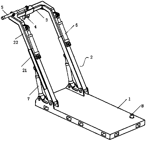
[0028] In this embodiment, the A-type gantry base for wave compensation ships is a four-degree-of-freedom A-shaped gantry for wave compensation ships. 3.

[0029] A telescopic frame 2 is arranged on the upper surface of one end of the base 1 , and an attitude sensor 8 is also arranged on the upper surface of the base 1 .

[0030] The telescopic frame 2 includes a swing frame 21 that is hinged with the base 1 and symmetrically arranged on both sides of the base 1, and the swing frame 21 can rotate around a plane, and the inner cavity of the other end of the swing frame 21 is sleeved with a movable frame 22; 3 is fixedly connected with the movable frame 22 at the end far away from the swing frame 21, and the crossbeam 3 is slidably sleeved with a connector hanger 4, and the connector hanger 4 is fixedly connected with a driving connector hanger 4 for lateral movement along the beam 3 Beam servo hydraulic cylinder 5 with linear displacement sensor.

[0031] The A-type gantry ba...

Embodiment 2

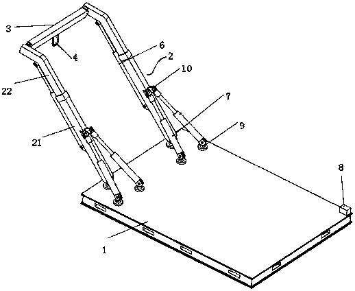
[0037] In this embodiment, the base of the A-type gantry for a wave compensation ship is an A-shaped gantry for a five-degree-of-freedom wave compensation ship, and the base of the A-type gantry for a wave compensation ship is arranged on the side of the hull; image 3 As shown, it includes a base 1, a telescopic frame 2 and a beam 3.

[0038] On both sides of the upper surface of one end of the base 1 are symmetrically distributed rotary pin groups, each rotary pin group includes three triangularly distributed rotary pins 9 , and the upper surface of the base 1 is also provided with an attitude sensor 8 .

[0039] The telescopic frame 2 includes a swing frame 21 symmetrically arranged on both sides of the base 1, and the swing pin 9 at the top angle in the swing pin group of the swing frame 21 is hinged, and the inner cavity of the other end of the swing frame 21 is sleeved with a movable frame 22; The two ends of 3 are connected to the movable frame 22 at the end far away fr...


PUM


Abstract

The invention relates to a wave-compensating marine A-type gate crane foundation arranged on the side of a hull and comprising a base, a telescopic frame and a cross beam; the telescopic frame is arranged on the upper surface at one end of the base; an attitude sensor is also arranged on the upper surface of the base; the telescopic frame includes two rockers hinged to the base and symmetrically arranged on two sides of the base, and a moving rack is nested in an inner cavity at the other end of each rocker; the cross beam is connected with the moving racks at the ends far away from rockers; the cross beam is also provided with a connector hanger. The wave-compensating marine A-type gate crane foundation also comprises servo driving mechanism A that drives the moving racks to expand alongthe rockers, servo driving mechanism B that drives the telescopic frame to rock, and servo driving mechanism C that drives the connector hanger to transversely move along the cross beam. The wave-compensating marine A-type gate crane foundation has the advantages that the foundation helps hoist and reclaim equipment safely and stably under terrible sea condition.

Description

technical field [0001] The invention belongs to the technical field of ship engineering, and relates to an A-type gantry for offshore ships, in particular to an A-type gantry base for a wave compensation ship. Background technique [0002] All kinds of unmanned submersibles are important tools for human beings to develop the ocean. As an important supporting equipment, the lifting system plays a decisive role in the efficiency of ocean operations. At present, the application of various retractable systems for offshore ships has become very popular, and the most typical lifting device is the A-type gantry. [0003] The existing A-type gantry mainly performs simple heave and wave compensation through the supporting constant tension winch and the retraction and release of the suspension cable, so most of them can only be operated in low sea conditions, which cannot meet the production work needs of people in high sea conditions; There are also some A-type gantry mounts with an...

Claims


Application Information

Patent Timeline
Patent Type & Authority Applications(China)
IPC IPC(8): B66C5/02B66C13/06F15B11/16F15B13/16
CPCB66C5/02B66C13/06B66C13/066B66C23/53F15B11/161F15B13/16
Inventor 卢道华王超权贺王佳
Owner JIANGSU UNIV OF SCI & TECH
Why Eureka
Try Eureka