
A jacking device for a crane

A technology of jacking devices and cranes, which is applied in the direction of lifting devices, lifting frames, etc., can solve the problems of long construction period, increased construction difficulty and risk, stop construction on site, etc., and achieve easy on-site adjustment, time saving and economic cost Effect

Active Publication Date: 2020-03-27
SHANGHAI ZHENHUA HEAVY IND +1
View PDF5 Cites 0 Cited by
  • Summary
  • Abstract
  • Description
  • Claims
  • Application Information

AI Technical Summary

Problems solved by technology

[0005] 1. The upper part of the bridge crane is heavy, so it is necessary to use a large-tonnage truck crane to lift the upper part of the crane;
[0006] 2. During the construction process, due to the shaking and rotation of the upper structure in the air, after the heightening column is inserted, it is difficult to accurately locate and complete the connection; after the connection is completed, the accuracy is not good
[0007] 3. The wind speed requirements on the construction site are relatively high. When the side wind on the site is slightly stronger, the difficulty and risk of construction will be greatly increased, or the construction site will be stopped;
[0008] 4. The construction period is long and difficult, and the rental cost of large-tonnage truck cranes is high, resulting in high construction costs for the entire project

Method used


Image

  • A jacking device for a crane
  • A jacking device for a crane
  • A jacking device for a crane

Examples


Embodiment Construction

[0032] The technical solutions of the present invention will be further described below in conjunction with the accompanying drawings and embodiments.

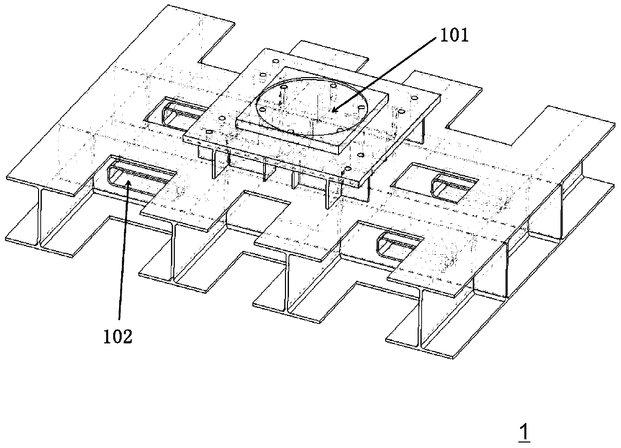
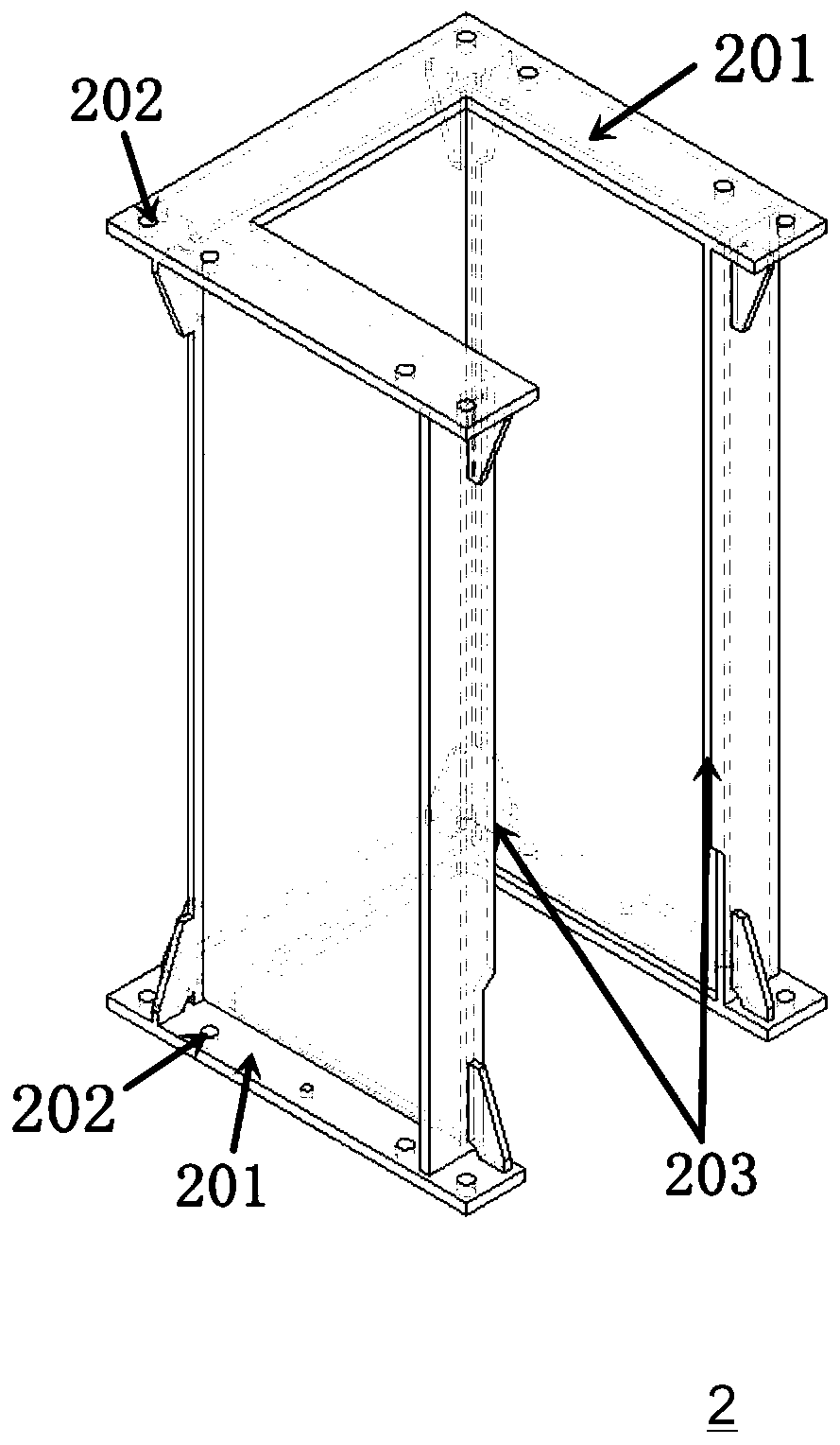
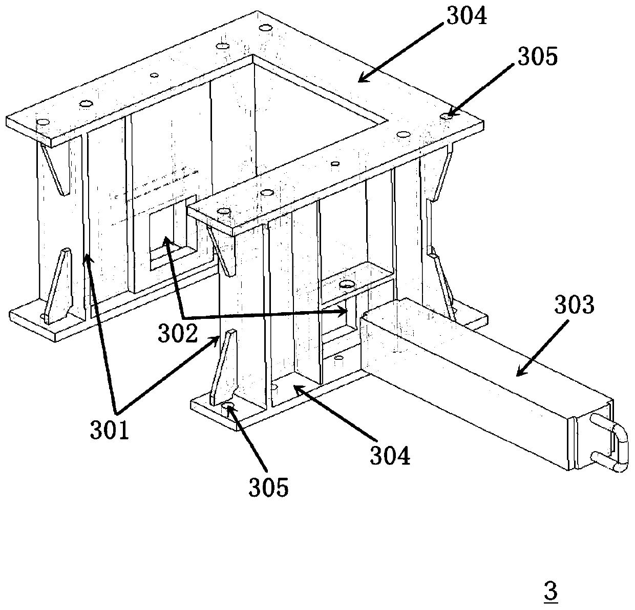
[0033] Please combine Figure 1 to Figure 6 As shown, a jacking device for a crane provided by the present invention includes: a jacking assembly 4, the jacking assembly 4 is arranged in a rectangular frame structure, and the four right-angled positions of the rectangular frame structure are connected successively below There are heightening short column 3, fixed column 2 and base 1, and heightening short column 3 can be connected several.

[0034] Preferably, the jacking assembly 4 includes: jacking beams 402, jacking columns 401, long connecting rods 405 and short connecting rods 406 connected with each other by high-strength bolts, and there are four jacking beams 402, located at Four right-angle positions of the rectangular frame structure, each jacking beam 402 is connected longitudinally by a long connecting rod 405 and...


PUM


Abstract

The invention discloses a jacking device for a crane. The jacking device for the crane includes a jacking assembly, the jacking assembly is arranged to be of a rectangular frame structure, heightenedshort vertical columns, fixed vertical columns and bases are separately connected under the four right angle positions of the rectangular frame structure in sequence. The jacking assembly comprises four jacking beams, jacking vertical columns, long connecting roads and short connecting rods, the four jacking beams are separately arranged at the four right angle positions of the rectangular frame structure, the rectangular frame structure is formed between each of the jacking beams through the long connecting rods and the short connecting rods, and the jacking vertical columns are connected under each jacking beam. Each heightened short vertical column comprises a [pi]-shaped structure formed by connecting three web plates, an opening is formed in one side face of each [pi]-shaped structure, two web plates opposite to each other are both provided with through holes, and the through holes can accommodate the jacking beams. Each jacking vertical column comprises a box-shaped structure formed by connecting four web plates, through holes are formed in the lower ends of the box-shaped structures, and the through holes can accommodate the jacking beams. According to the jacking device forthe crane, the working efficiency can be improved effectively, easy adjustment for site construction is achieved, and the requirements for site construction conditions are relatively low.

Description

technical field [0001] The invention relates to crane auxiliary equipment, and more specifically relates to a jacking device for a crane, which can be applied to working occasions such as installation, general assembly, transformation, repair, disassembly of cranes and large steel structures. Background technique [0002] Due to the rapid development of trade globalization, the current throughput of container terminals has increased rapidly, resulting in a large number of dock cranes in service unable to meet the current container yard, loading and unloading needs. Taking wheeled container gantry cranes (hereinafter referred to as yard cranes) as an example, the requirements for storage yards and spans of container terminals are getting higher and higher, which makes the current yard bridges more and more unable to meet the production needs of the terminals. In order to adapt to the current production status, it has become an urgent choice for many wharves to upgrade the exi...

Claims


Application Information

Patent Timeline
Patent Type & Authority Patents(China)
IPC IPC(8): B66F7/16B66F7/20B66F7/28
CPCB66F7/16B66F7/20B66F7/28
Inventor 熊丁根王芝斌苏红亚封志文沈锋周东波
Owner SHANGHAI ZHENHUA HEAVY IND
Learn More