Computer case

A computer mainframe and mainframe technology, which is applied in the direction of supporting machines, mechanical equipment, machine platforms/supports, etc., can solve the problems of poor cushioning performance and inconvenient installation, and achieve the effects of enhanced elasticity, high practicability, and convenient installation

Active Publication Date: 2018-08-24
深圳市麦凯莱科技有限公司
View PDF9 Cites 13 Cited by
  • Summary
  • Abstract
  • Description
  • Claims
  • Application Information

AI Technical Summary

Problems solved by technology

[0002] Computer cases are more common in daily life. Present computer cases generally include a case body, a main board arranged in the case body, a hard disk, and a cooling fan. After retrieval, the authorized announcement number is a computer main case disclosed by CN205485852U, including rollers. , the chassis body, the motherboard, hard disk and cooling fan arranged in the chassis body, the hard disk, cooling fan and the motherboard are electrically connected, the chassis body is provided with a pull rod, and each corner of the bottom of the chassis body is respectively provided with a buffer. The bottom is provided with a height-adjusting sleeve, and the bottom of the height-adjusting sleeve is provided with a horizontal plate. The rollers are installed on the bottom of the horizontal plate. Its height is adjustable and practical, but its cushioning performance is poor and it is not easy to install, so We propose a computer mainframe to solve the above problems

Method used


Image

  • Computer case
  • Computer case
  • Computer case

Examples


Embodiment 1

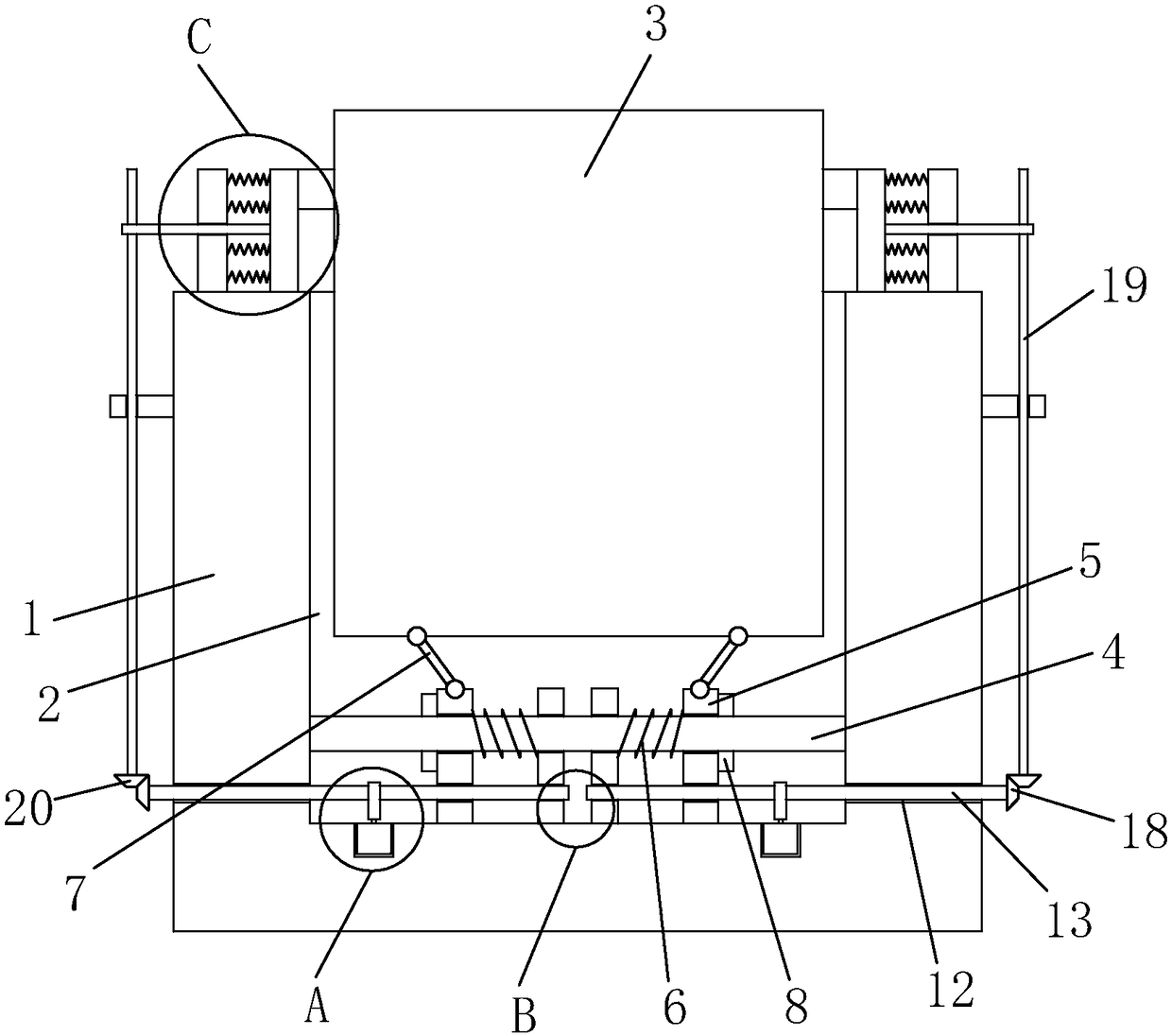
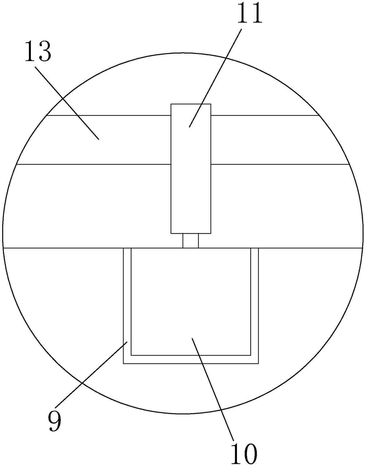
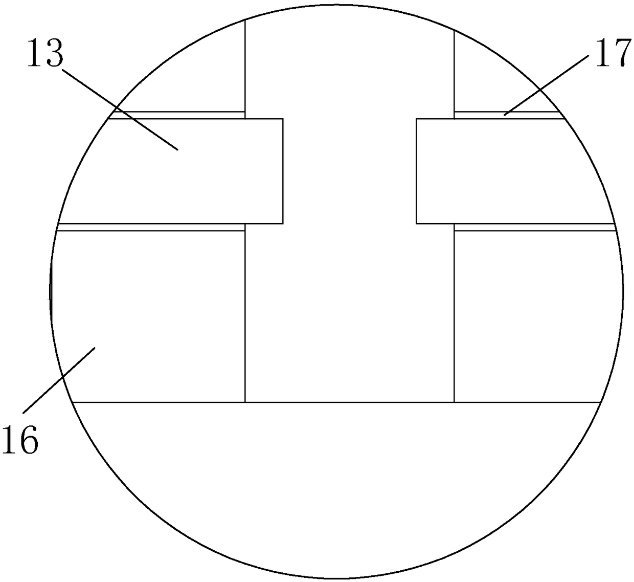
[0048] refer to Figure 1-5 In this embodiment, a main computer box is proposed, including a mounting base 1 and a first mounting groove 2 opened on the top of the mounting base 1, a main chassis body 3 is installed in the first mounting groove 2, and the first mounting groove 2 The same fixed column 4 located below the main box body 3 is welded on the inner walls of both sides. Two first moving plates 5 are slidably sleeved on the fixed column 4, and the sides of the two first moving plates 5 are welded to each other. The buffer spring 6 sleeved on the fixed column 4, the top of the first moving plate 5 is hinged with one end of the drawbar 7, and the other ends of the two drawbars 7 are hinged at the bottom of the main chassis body 3, the first installation groove 2 There are two second installation grooves 9 on the inner wall of the bottom of the bottom, and a push rod motor 10 is installed in the second installation groove 9, and a push plate 11 is welded on the output sha...

Embodiment 2

[0052] refer to Figure 6-13 , this embodiment also includes the following features on the basis of Embodiment 1: a motherboard is installed in the main chassis body, a CPU and an independent graphics card are installed on the motherboard; an aluminum alloy is installed on the CPU or / and the independent graphics card material heat sink. The heat sink is connected with a cooling assembly; the cooling assembly includes a radiator 90 and a liquid pump 80 for delivering cooling liquid to circulate between the heat sink and the radiator. The radiator is installed on the upper side wall or top of the main chassis body.

[0053] The liquid pump includes a pump casing, a cover body sealingly connected to the open end of the pump casing, a water wheel installed in the pump casing to rotate, and a servo motor connected to the outside of the pump casing to drive the water wheel to rotate through magnetic transmission.

[0054] An overall U-shaped fixing belt 84 for fixing the servo mot...


PUM


Abstract

The invention discloses a computer case. The computer case comprises a mounting seat and a first mounting groove formed in the top of the mounting seat, wherein the first mounting groove is internallyprovided with a case body; a fixed leg below the case body is welded on inner walls at two sides of the first mounting groove; two first movable plate are sleeved on the fixed leg in a sliding manner; buffer springs sleeved on the fixed leg are welded on sides, close to each other, of the two first movable plate; the tops of the first movable plates are hinged with one ends of dragging rods; theother ends of the two dragging rods are hinged with the bottom of the case body; two second mounting grooves are formed in the bottom inner wall of the first mounting groove; and push rod motors are mounted in the second mounting grooves. The computer case is high in practicability; through second movable plates and the buffer springs, elasticity of the buffer springs is strengthened so that the case body can be effectively buffered; and through a connection plate and a rubber column, the mounting of the case body is facilitated.

Description

technical field [0001] The invention relates to the technical field of main box, in particular to a computer main box. Background technique [0002] Computer cases are more common in daily life. Present computer cases generally include a case body, a main board arranged in the case body, a hard disk, and a cooling fan. After retrieval, the authorized announcement number is a kind of computer main body case disclosed by CN205485852U, including a roller , the chassis body, the motherboard, hard disk and cooling fan arranged in the chassis body, the hard disk, cooling fan and the motherboard are electrically connected, the chassis body is provided with a pull rod, and each corner of the bottom of the chassis body is respectively provided with a buffer. The bottom is provided with a height-adjusting sleeve, and the bottom of the height-adjusting sleeve is provided with a horizontal plate. The rollers are installed on the bottom of the horizontal plate. Its height is adjustable a...

Claims


Application Information

Patent Timeline
IPC IPC(8): G06F1/18G06F1/20F16M11/04F16M11/18F16F15/04F16F15/08
CPCF16F15/04F16F15/08F16M11/043F16M11/18G06F1/181G06F1/20G06F2200/1638G06F2200/201
Inventor 吴彦均
Owner 深圳市麦凯莱科技有限公司
Why Eureka
Try Eureka