Anti-releasing socket
A socket and a combination technology, applied in the direction of electrical components, coupling devices, circuits, etc., can solve problems such as electric shock and easy falling of children
- Summary
- Abstract
- Description
- Claims
- Application Information
AI Technical Summary
Problems solved by technology
Method used
Image
Examples
Embodiment 1
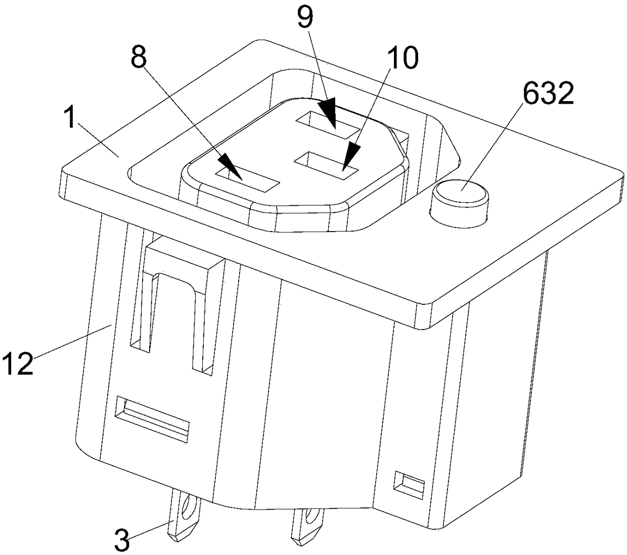
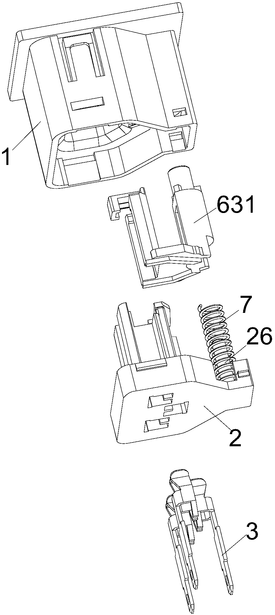
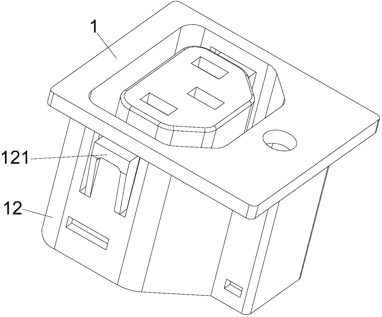
[0038] In this embodiment, an anti-off socket, such as figure 1 , figure 2 and Figure 10 As shown, it includes an upper cover 1, a base 2, a conductive sheet 3, an A card 4, a B card 5, a driving member 6 and a spring 7, and the upper cover 1 and the base 2 are buckled together to form a socket shell, as Figure 5 As shown, the base 2 is provided with a live wire slot 21, a neutral wire slot 22 and a ground wire slot 23, as image 3 and Figure 4 As shown, through holes are respectively provided on the above-mentioned upper cover 1 corresponding to the live wire slot 21, the neutral wire slot 22 and the ground wire slot 23 to form a live wire plug with the above-mentioned live wire slot 21, the neutral wire slot 22 and the ground wire slot 23 respectively. Hole 8, neutral wire jack 9 and ground wire jack 10, are all provided with conductive sheet 3 in live wire jack 8, neutral wire jack 9 and ground wire jack 10, at this moment, the present invention forms and existing T...
Embodiment 2
[0044] This embodiment is further improved on the basis of Embodiment 1. In this embodiment, as Image 6 , Figure 7 , Figure 8 as well as Figure 10 As shown, a connection plate 64 is also provided between the above-mentioned A column 61 and B column 62, and the upper end of the connection plate 64 is provided with a square groove 66 that is compatible with the above-mentioned ground wire jack 10. When the present invention is installed, The above-mentioned square groove 66 is located directly above the above-mentioned ground wire groove 23, so that the ground wire jack 10 is more standardized, which is beneficial for users to insert the ground wire pin.
[0045] Furthermore, in this embodiment, as Figure 10 As shown, when the present invention is in the normal state (that is, when the A column 61 withstands the A card 4, and the B column 62 withstands the B card 5), the above-mentioned A card 4 and the B card 5 are far from the end of the above-mentioned ground wire slo...
Embodiment 3
[0047] This embodiment is further improved on the basis of embodiment 2. In this embodiment, as Figure 7 , Figure 10 and Figure 11 As shown, the above-mentioned connecting plate 64 is provided with a convex strip 65, and the convex strip 65 is arranged on the groove wall of the above-mentioned square groove 66, and after installation, the convex strip 65 is just inserted into the above-mentioned A card 4 and B Between the cards 5, the width of the convex strip 65 is defined to be smaller than the gap width between the A card 4 and the B card 5, so as to leave a margin for the movement of the A card 4 and the B card 5, and the convex strip 65 is defined to protrude from the connecting plate The height of 64 is smaller than the width of the above-mentioned A card 4 and B card 5 (that is, smaller than the length of the above-mentioned gap), so as to prevent the protruding strip 65 from blocking the ground wire insertion hole 10 .
[0048] Through this structure, when the abo...
PUM
 Abstract
Description
Claims
Application Information
 - R&D
- Intellectual Property
- Life Sciences
- Materials
- Tech Scout
- Unparalleled Data Quality
- Higher Quality Content
- 60% Fewer Hallucinations
Browse by: Latest US Patents, China's latest patents, Technical Efficacy Thesaurus, Application Domain, Technology Topic, Popular Technical Reports.
© 2025 PatSnap. All rights reserved.Legal|Privacy policy|Modern Slavery Act Transparency Statement|Sitemap|About US| Contact US: help@patsnap.com


