Sleeve-type safety clip and high-voltage switch cabinet

A safety clip and sleeve-type technology, which is applied in the field of electrical equipment, can solve the safety and hidden dangers that the insulation baffle is easily opened by mistake, so as to avoid electric shock and improve operation safety.

Pending Publication Date: 2018-08-24
GUANGDONG POWER GRID CO LTD +1
View PDF6 Cites 5 Cited by
  • Summary
  • Abstract
  • Description
  • Claims
  • Application Information

AI Technical Summary

Problems solved by technology

[0006] The purpose of the present invention is to provide a sleeve-type safety clip to solve the technical problem existing in the prior art that the insulating baffle of the switch cabinet is easily opened by mistake and thus has serious potential safety hazards
[0007] The purpose of the present invention is also to provide a high-voltage switchgear to solve the technical problem existing in the prior art that the insulating baffles of the switchgear are easily opened by mistake, resulting in serious safety hazards

Method used


Image

  • Sleeve-type safety clip and high-voltage switch cabinet
  • Sleeve-type safety clip and high-voltage switch cabinet
  • Sleeve-type safety clip and high-voltage switch cabinet

Examples


Embodiment 1

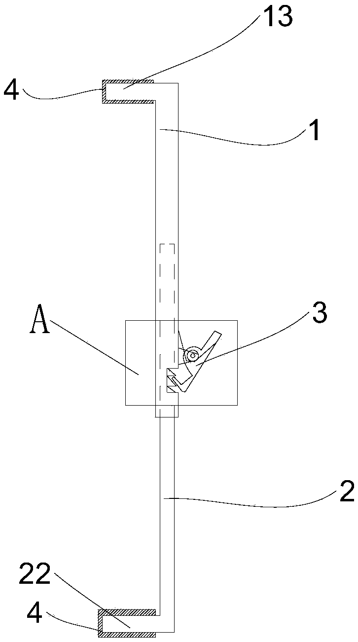
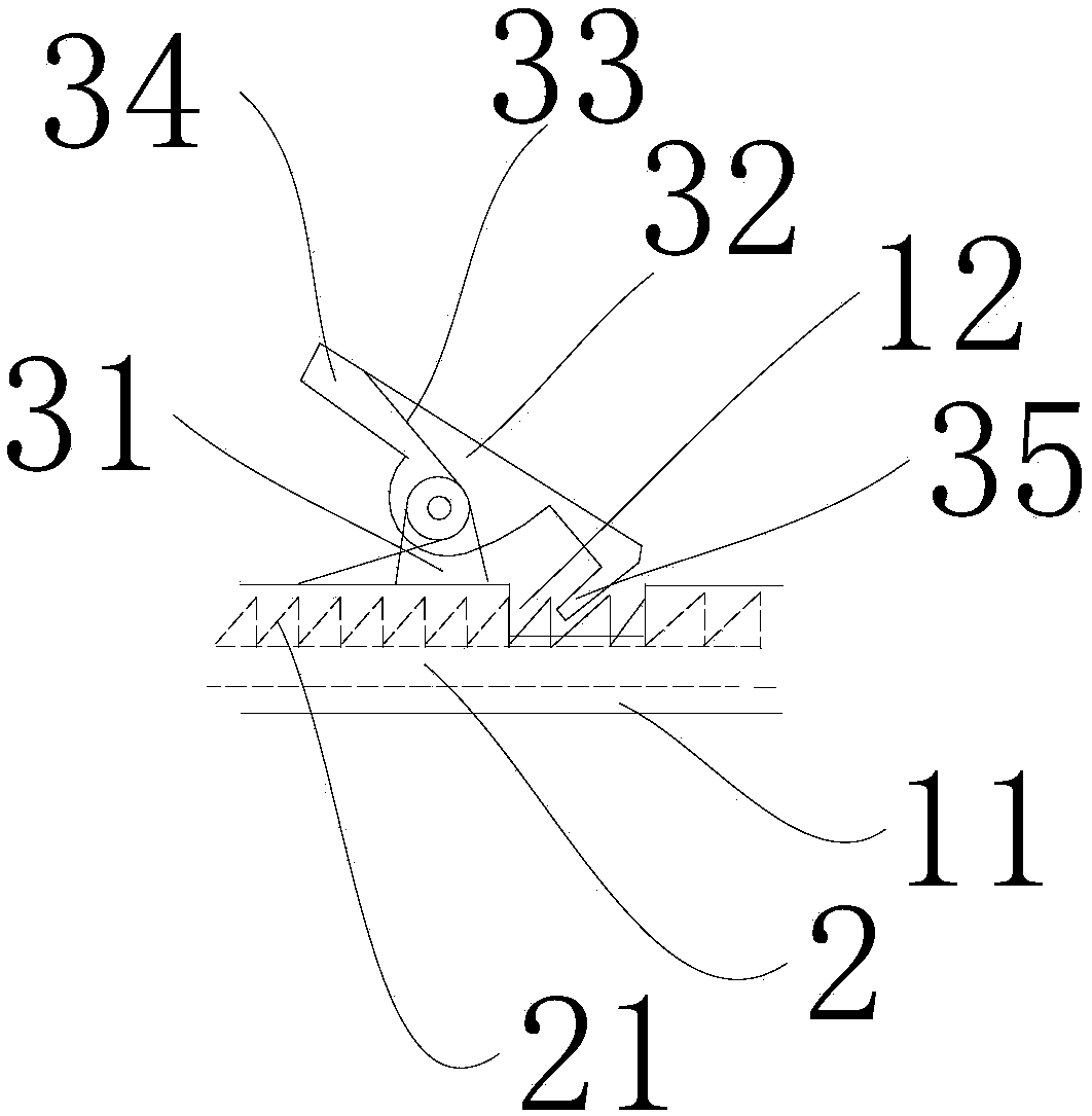
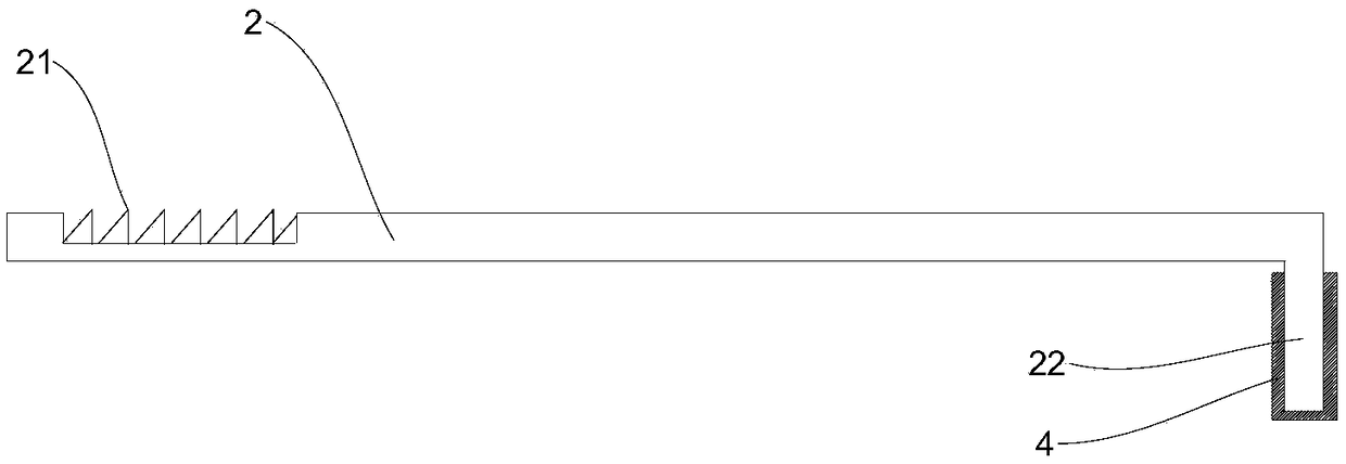
[0044] see Figure 1 to Figure 4 As shown, this embodiment provides a sleeve-type safety clip including a first clamping rod 1 , a second clamping rod 2 and a fixing assembly.

[0045] One end of the first clamping rod 1 is provided with a sleeve 11, the axial direction of the sleeve 11 is consistent with the extension direction of the first clamping rod 1, and one end of the second clamping rod 2 is inserted into the sleeve 11 and the second clamping rod 2 can slide along the axial direction of the sleeve 11, and the ends of the first clamping rod 1 and the second clamping rod 2 away from the sleeve 11 are respectively provided with pressing The clamping assembly of the insulating baffle. The fixing assembly is used to limit the relative movement between the second clamping rod 2 and the sleeve 11 .

[0046] It can be understood that the sleeve 11 is preferably formed by a hollow structure at the end of the first clamping rod 1 close to the second clamping rod 2, that is, t...

Embodiment 2

[0073] This embodiment provides a high-voltage switchgear, including a switchgear body and the sleeve-type safety clip described in Embodiment 1.

[0074] The switchgear body includes an upper contact box and a lower contact box, an upper insulating baffle is arranged above the upper contact box, and a lower insulating baffle is arranged below the lower contact box.

[0075] The clamping assembly of the first clamping rod 1 presses on the upper edge of the upper insulating baffle, and the clamping assembly of the second clamping rod 2 presses on the lower edge of the lower insulating baffle. Or, the clamping assembly of the first clamping rod 1 presses on the lower edge of the lower insulating baffle, and the clamping assembly of the second clamping rod 2 presses on the upper edge of the upper insulating baffle.

[0076]Preferably, the clamping assembly of the first clamping rod 1 is pressed in the middle of the lengthwise direction of the upper insulating baffle, and the clam...


PUM


Abstract

The invention relates to the technical field of electrical equipment and discloses a sleeve-type safety clip and a high-voltage switch cabinet. The sleeve-type safety clip comprises a first clamping rod, a second clamping rod and a fixing assembly, wherein one end of the first clamping rod is provided with a sleeve; the axial direction of the sleeve is consistent with the extending direction of the first clamping rod; one end of the second clamping rod is inserted in the sleeve and can slide along the axial direction of the sleeve; one end, away from the sleeve, of each of the first clamping rod and the second clamping rod is provided with a clamping assembly; and the fixing assembly is used for limiting relative movement between the second clamping rod and the sleeve. an upper insulationbaffle and a lower insulation baffle are fixed through the sleeve-type safety clip, the problem of electric shock caused as the insulation baffle is opened mistakenly can be effectively solved, and the operation safety of an operator is improved.

Description

technical field [0001] The invention relates to the technical field of electrical equipment, in particular to a sleeve-type safety clip and a high-voltage switch cabinet. Background technique [0002] The switch cabinet is a kind of electrical equipment. The external line of the switch cabinet first enters the main control switch in the cabinet, and then enters the sub-control switch, and each branch is set according to its needs. Such as instruments, automatic controls, motor magnetic switches, various AC contactors, etc., some also have high-voltage room and low-voltage room switch cabinets, high-voltage busbars, such as power plants, etc. load shedding. [0003] The main function of switchgear is to switch, control and protect electrical equipment during the process of power generation, transmission, distribution and power conversion in the power system. The components in the switch cabinet are mainly composed of circuit breakers, disconnectors, load switches, operating...

Claims


Application Information

Patent Timeline
Patent Type & Authority Applications(China)
IPC IPC(8): H02B1/14
CPCH02B1/14
Inventor 林旭毅
Owner GUANGDONG POWER GRID CO LTD
Why Eureka
Try Eureka