Monitoring system and application method thereof
A monitoring system and control module technology, applied in closed-circuit television systems, components of television systems, televisions, etc., can solve problems such as difficulty in erection, crossed and mixed working lines, etc.
- Summary
- Abstract
- Description
- Claims
- Application Information
AI Technical Summary
Problems solved by technology
Method used
Image

Examples
Embodiment 1
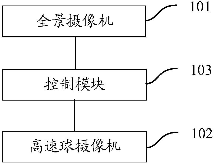
[0079] Such as figure 1 As shown, a monitoring system provided by an embodiment of the present invention includes: a panoramic camera 101, a speed dome camera 102 and a control module 103; wherein,
[0080] The panoramic camera 101 is used to collect panoramic monitoring images of designated areas;
[0081] The control module 103 is configured to acquire trigger information of any target area in the panoramic monitoring image, generate a control instruction corresponding to the high-speed dome camera according to the trigger information, and send the control instruction to the high-speed dome camera. dome camera;
[0082] The high-speed dome camera 102 is configured to collect target surveillance images of the target area according to the control instruction.
[0083] When in use, the surveillance image of the designated area is collected through the panoramic camera. Since the panoramic camera can monitor the scene without blind spots, it can achieve a large viewing angle a...
Embodiment 2
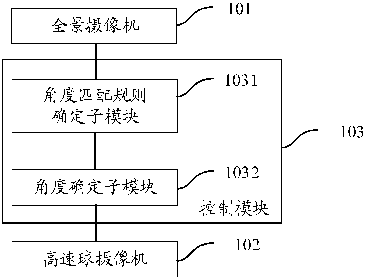
[0086] Such as figure 2 As shown, the second embodiment is basically the same as the first embodiment, and the similarities will not be repeated. The difference lies in:
[0087] The control module 103 includes: an angle matching rule determination submodule 1031 and an angle determination submodule 1032; wherein,
[0088] The angle matching rule determination submodule 1031 is configured to determine an angle matching rule according to at least two monitoring data pairs acquired in advance; wherein each monitoring data pair includes: a sample position of any sample position in the designated area Coordinates, and the pitch angle of the sample when the high-speed dome camera performs image acquisition on the sample position;
[0089] The angle determination sub-module 1032 is configured to determine the pitch angle of the target corresponding to the speed dome camera according to the angle matching rule and the target position coordinates of the target area carried in the tr...
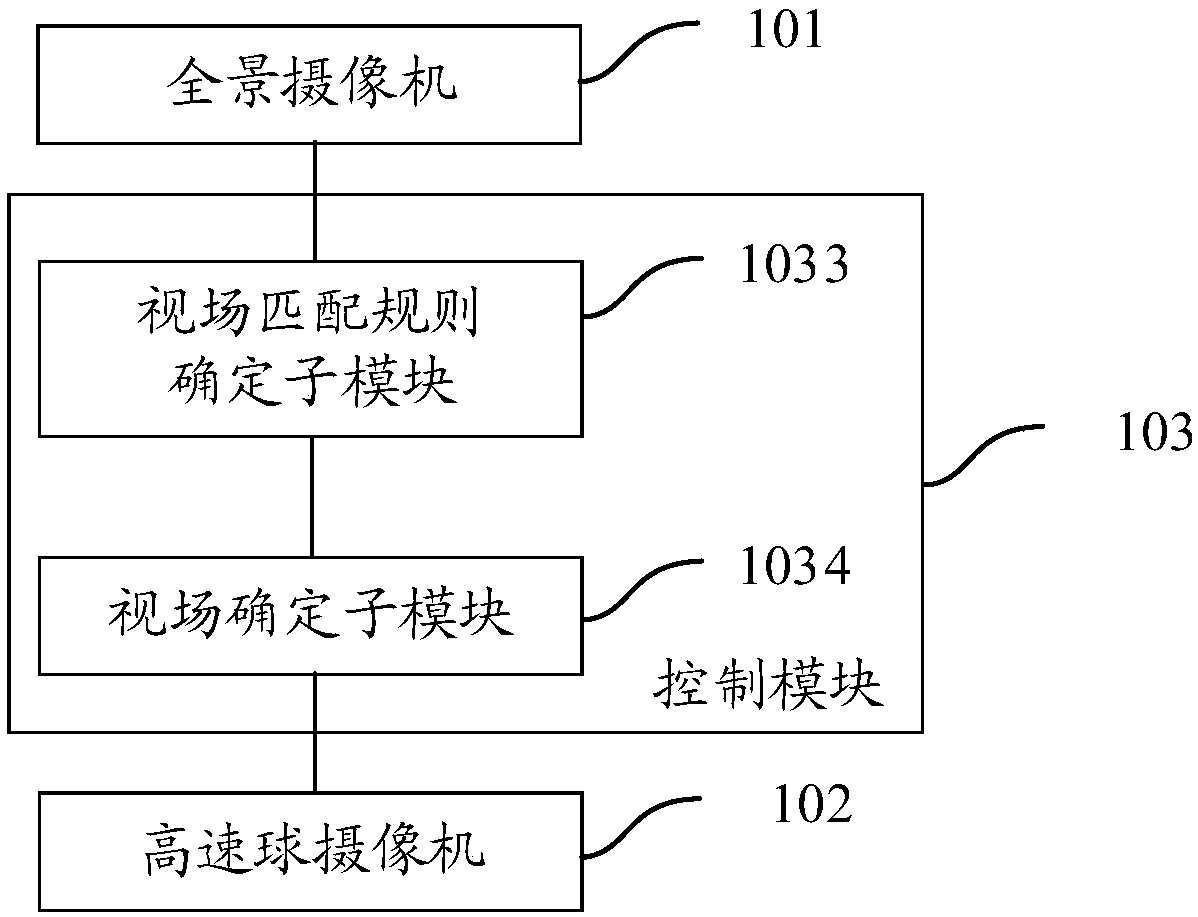
Embodiment 3
[0097] The third embodiment is basically the same as the second embodiment, and the similarities will not be repeated. The difference lies in:
[0098] The angle matching rule determining subunit 1031 is further configured to determine the current pitch angle corresponding to each of the sample position coordinates according to the angle matching coefficient, and determine each of the current pitch angles and the corresponding sample pitch angle between the data errors; determine whether there is at least one of the data errors greater than a preset threshold, if not, send the angle matching coefficient to the angle determination submodule.
[0099] Here, after solving the angle matching coefficient, the sample position coordinates in each monitoring data pair can be brought into the equations to obtain the current pitch angle corresponding to the sample position coordinates under the current angle matching coefficient, and determine the current The data error between the pitc...
PUM
 Abstract
Description
Claims
Application Information
 - R&D
- Intellectual Property
- Life Sciences
- Materials
- Tech Scout
- Unparalleled Data Quality
- Higher Quality Content
- 60% Fewer Hallucinations
Browse by: Latest US Patents, China's latest patents, Technical Efficacy Thesaurus, Application Domain, Technology Topic, Popular Technical Reports.
© 2025 PatSnap. All rights reserved.Legal|Privacy policy|Modern Slavery Act Transparency Statement|Sitemap|About US| Contact US: help@patsnap.com