
Motor drive device and motor drive method

A technology for driving devices and electric motors, which is applied in starting devices, motor control, electronic commutation motor control, etc., and can solve problems such as the deterioration of working sound and radio noise, and the inability to adjust the advance angle.

Active Publication Date: 2018-08-24
MITSUBA CORP
View PDF6 Cites 1 Cited by
  • Summary
  • Abstract
  • Description
  • Claims
  • Application Information

AI Technical Summary

Problems solved by technology

Therefore, it is impossible to drive at an advance angle of less than 30 degrees, for example, an advance angle of 15 to 20 degrees (conduction angle of 130 degrees), so the advance angle cannot be adjusted, and operational sounds and radio noises will occur when actually mounted on a vehicle. worsening problem

Method used


Image

  • Motor drive device and motor drive method
  • Motor drive device and motor drive method
  • Motor drive device and motor drive method

Examples


Embodiment Construction

[0029] Hereinafter, the present invention will be described through embodiments of the invention, but the following embodiments do not limit the invention according to the claims. In addition, not all combinations of features described in the embodiments are essential to the technical means for solving the technical problems of the present invention. In the drawings, the same reference numerals are sometimes attached to the same or similar parts, and repeated explanations are omitted. In the drawings, in order to clarify the shape, size, etc. of elements, they may be exaggerated in some cases.

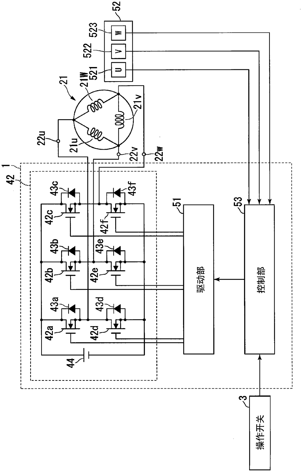
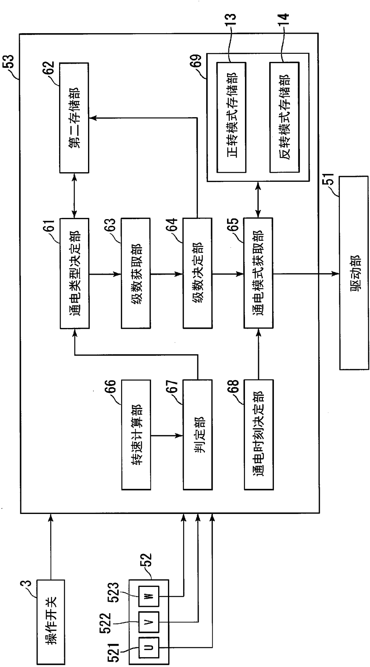
[0030] The motor drive device in the embodiment supplies current to a plurality of coils to rotate the rotor. The motor drive device includes: a plurality of detection sensors provided at different phases in the rotation direction of the rotor, and detecting the phases in the rotation direction of the rotor to generate an output signal; a determination unit that determines the positi...


PUM


Abstract

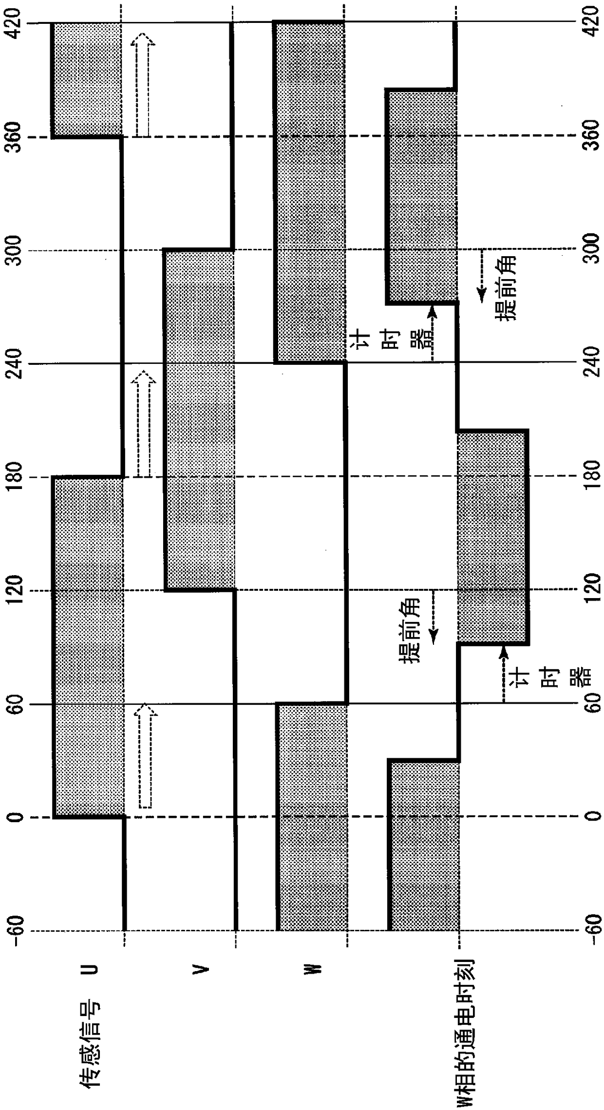
The present invention provides a motor drive device and a motor drive method. This motor drive device is provided with: a stage determination unit which determines the position of a rotor on the basisof the combination of the states of multiple output signals; and an energization timing determination unit which, at the time of start of a motor, sets, as an energization timing at which a coil is energized, a timing advanced by an amount equivalent to a predetermined electrical angle, wherein, when the rotation speed of the motor becomes equal to or higher than a predetermined rotation speed, the energization timing determination unit sets, as the energization timing, a timing when a predetermined period of time has elapsed after the position of the rotor reaches a position for an electrical angle corresponding to a displacement amount of an arbitrarily advanced electrical angle relative to the predetermined electrical angle by which the advancement has been made at the time of the start.

Description

technical field [0001] The invention relates to a motor driving device and a motor driving method. [0002] This application claims priority based on Japanese Patent Application No. 2016-020157 filed on February 4, 2016, and the content of this patent application is cited herein. Background technique [0003] Conventionally, when driving a brushless motor, a motor drive device sets the mechanical advance angle to 0 degrees, and drives the brushless motor by changing the advance angle through software. Specifically, the motor drive device acquires sensing signals respectively corresponding to U phase, V phase, and W phase of the brushless motor from detection sensors (for example, Hall ICs) that detect the rotational position of the motor. [0004] Then, the motor drive device identifies the stage number based on the acquired sensing signal, reads the energization pattern corresponding to the stage number, and after the specified rotation position (for example, 30 degrees in...

Claims


Application Information

Patent Timeline
Patent Type & Authority Applications(China)
IPC IPC(8): H02P6/20
CPCH02P6/20H02P2203/03H02P6/153G05B19/4015
Inventor 小岛直希小林知史川崎敦史
Owner MITSUBA CORP
Learn More