
Spine arching waist and lumbar disc posterior protrusion jacking and load-bearing posture correction brace

A lumbar disc and spine technology, applied in the field of spinal bow and lumbar disc posterior protrusion relying on weight-bearing posture correction braces, can solve the problems of poor practicability or comfort of the shoulders and arms, and large pulling force, etc. Low, simple structure effect

Inactive Publication Date: 2018-08-28
丁世卫
View PDF0 Cites 0 Cited by
  • Summary
  • Abstract
  • Description
  • Claims
  • Application Information

AI Technical Summary

Problems solved by technology

[0002] Existing spinal arch correction braces use steel hard or metal plates to support the spine for correction of stress. The waist belt is installed on the left and right sides of the lower end of the spine board, and the left and right shoulders and arms of the upper body are maintained by the shoulder belt on the upper end of the spine board, and the waist and abdomen are maintained by the lower belt. The brace cannot be bent over during use and is not suitable for use in work and study environments, and this kind of correction brace uses its left and right shoulder straps to pull the shoulders backward, and the left and right shoulders are small in force and difficult to pull. The pulling force is high, and the shoulders and arms will become numb within a short period of time. The blood circulation is blocked. The practicality or comfort is poor, so it is not used by many sub-healthy groups. There is no simple and better solution at present.

Method used


Image

  • Spine arching waist and lumbar disc posterior protrusion jacking and load-bearing posture correction brace
  • Spine arching waist and lumbar disc posterior protrusion jacking and load-bearing posture correction brace
  • Spine arching waist and lumbar disc posterior protrusion jacking and load-bearing posture correction brace

Examples


Embodiment Construction

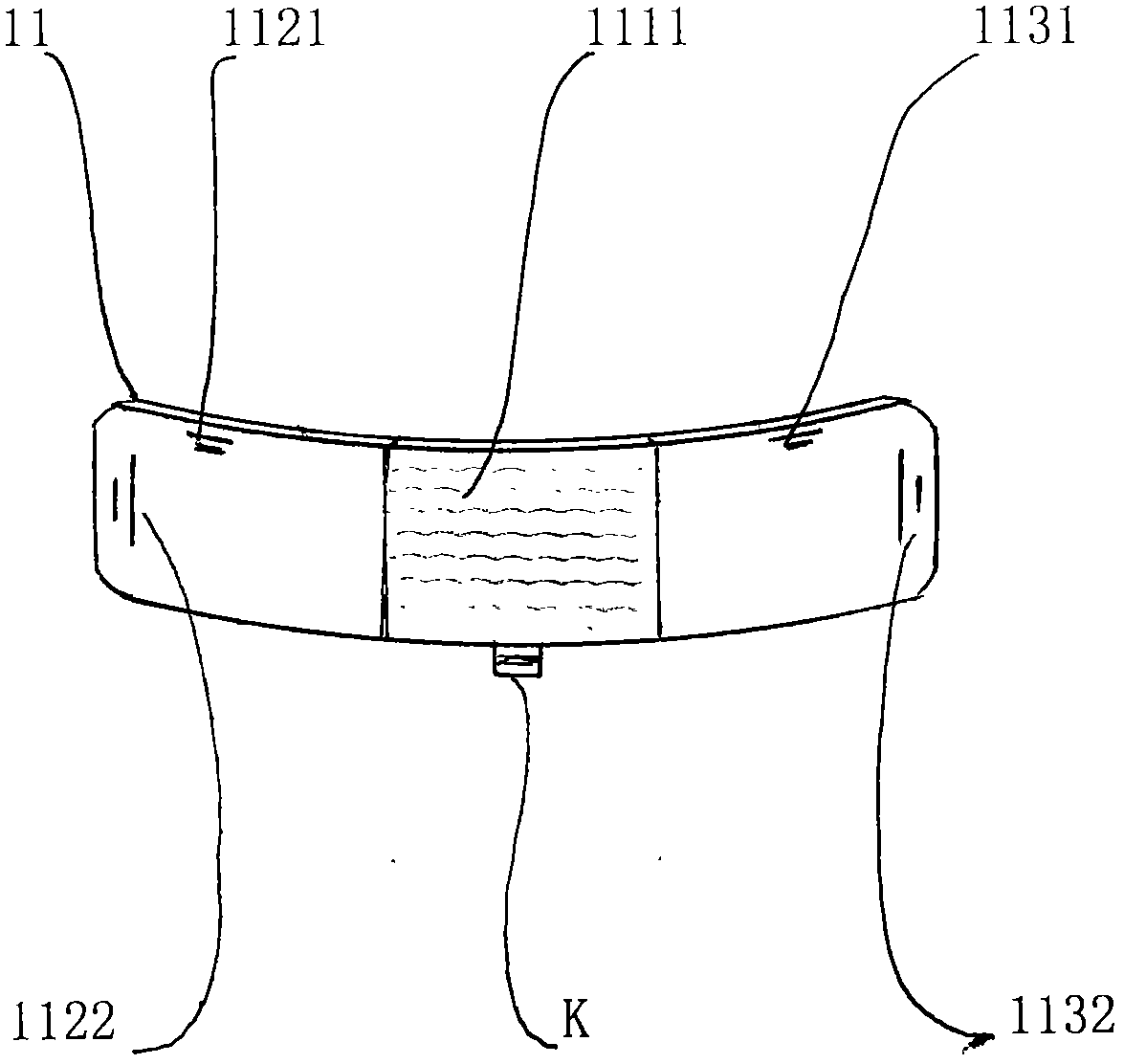
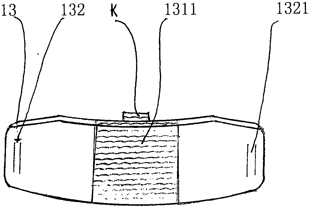
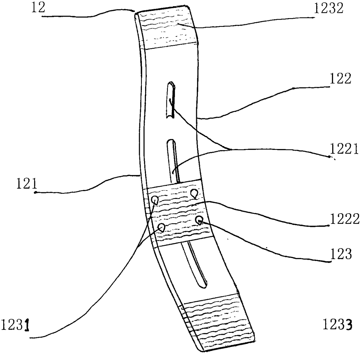
[0020] Such as Figure 1-6As shown, a kind of spine arch and lumbar disc protrusion top rests on a weight-bearing posture correction brace, including; .Abdominal belt 18. Left shoulder belt 18. Right shoulder belt 20; The upper edge plate 11 is in the shape of an elastic arc-shaped strip, the inner end surface 111 of the upper edge plate 11 is an arc-shaped concave surface 111, and a hook and loop is provided in the middle of the upper edge plate 11 1111, a drawstring K is provided on the sticky buckle 1111, the sticky buckle 1111 is fixedly connected with the upper edge plate 11 by glue or wrapping sewing, and a shoulder strap bolt 1121 is arranged on the upper end of the left wing 112 of the upper edge plate 11. The left end is provided with an abdominal belt bolt 1122, and the upper edge plate 11 right wing 113 is provided with a shoulder belt bolt 1131 at the upper end of the right wing 113. An abdominal belt bolt 1132 is arranged at the right end of the right wing 113. 1...


PUM


Abstract

The invention relates to a spine arching waist and lumbar disc posterior protrusion jacking and load-bearing posture correction brace which comprises a superomarginal plate, a spine plate, a lumbar vertebra plate, waistbands, a bellyband and shoulder straps, a pasting fastener is arranged in the middle of the superomarginal plate which is provided with the shoulder straps and the bellyband, a pasting fastener is arranged in the middle of the lumbar vertebra plate, the waistbands are arranged on band bolts at two ends, the inner end face of the spine plate is an arching face, a pasting fasteneris arranged at the upper end of the spine plate to be connected with the superomarginal plate, and an assistant band is arranged at a position, close to the middle, of the outer end of the spine plate. An arching waist is abutted through the arching face of the spine plate, the bellyband maintains an upper abdomen, the waistbands maintain a lower abdomen, a resultant force is formed at a front-rear buckling face peak of the upper body to promote the arching waist to forwards protrude, and jacking support force of the spine plate is enhanced through the assistant band, so that posture correction practicability is improved greatly; for lumbar disc posterior protrusion and lumbar muscle strain, the lumbar vertebra plate can be used for jacking intervention load-bearing waist protection balance.

Description

technical field [0001] The invention relates to a medical device, in particular to a weight-bearing posture correcting support for spinal arch and lumbar disc protrusion. Background technique [0002] Existing braces for correcting lumbar spine correct the spine through steel hard or metal plates, and the braces are all equipped with shoulder straps on the left and right sides of the upper end of a vertical spine plate. The waist belt is installed on the left and right sides of the lower end of the spine board, and the left and right shoulders and arms of the upper body are maintained by the shoulder belt on the upper end of the spine board, and the waist and abdomen are maintained by the lower belt. The brace cannot be bent over during use and is not suitable for work and study environments, and this kind of correction brace uses its left and right shoulder straps to pull the shoulders backward. The force-bearing surface of the left and right shoulders is small. If the pul...

Claims


Application Information

Patent Timeline
Patent Type & Authority Applications(China)
IPC IPC(8): A61F5/01
CPCA61F5/0102
Inventor 丁世卫
Owner 丁世卫
Learn More