Check patentability & draft patents in minutes with Patsnap Eureka AI!

An electric pin puller

A pin-puller, electric technology, applied in the direction of manufacturing tools, hand-held tools, etc., can solve the problems of uncontrollable power energy, difficult operation of the pin-pulling device, poor stability, etc. The effect of stability

Active Publication Date: 2019-12-10
AEROSPACE INST OF ADVANCED MATERIALS & PROCESSING TECH
View PDF5 Cites 0 Cited by
  • Summary
  • Abstract
  • Description
  • Claims
  • Application Information

AI Technical Summary

Problems solved by technology

[0004] The technical problem to be solved by the present invention is to solve the problems of difficult operation, poor stability and uncontrollable power energy during the pin pulling process of the existing pin pulling device

Method used


Image

  • An electric pin puller
  • An electric pin puller
  • An electric pin puller

Examples


Embodiment Construction

[0037] In order to make the purpose, technical solutions and advantages of the embodiments of the present invention clearer, the technical solutions in the embodiments of the present invention will be clearly and completely described below in conjunction with the drawings in the embodiments of the present invention. Obviously, the described embodiments It is a part of embodiments of the present invention, but not all embodiments. Based on the embodiments of the present invention, all other embodiments obtained by persons of ordinary skill in the art without making creative efforts belong to the protection scope of the present invention.

[0038] For ease of description, the orientation words "up" and "down" in this embodiment refer to the orientation of the electric pin puller in an upright working state.

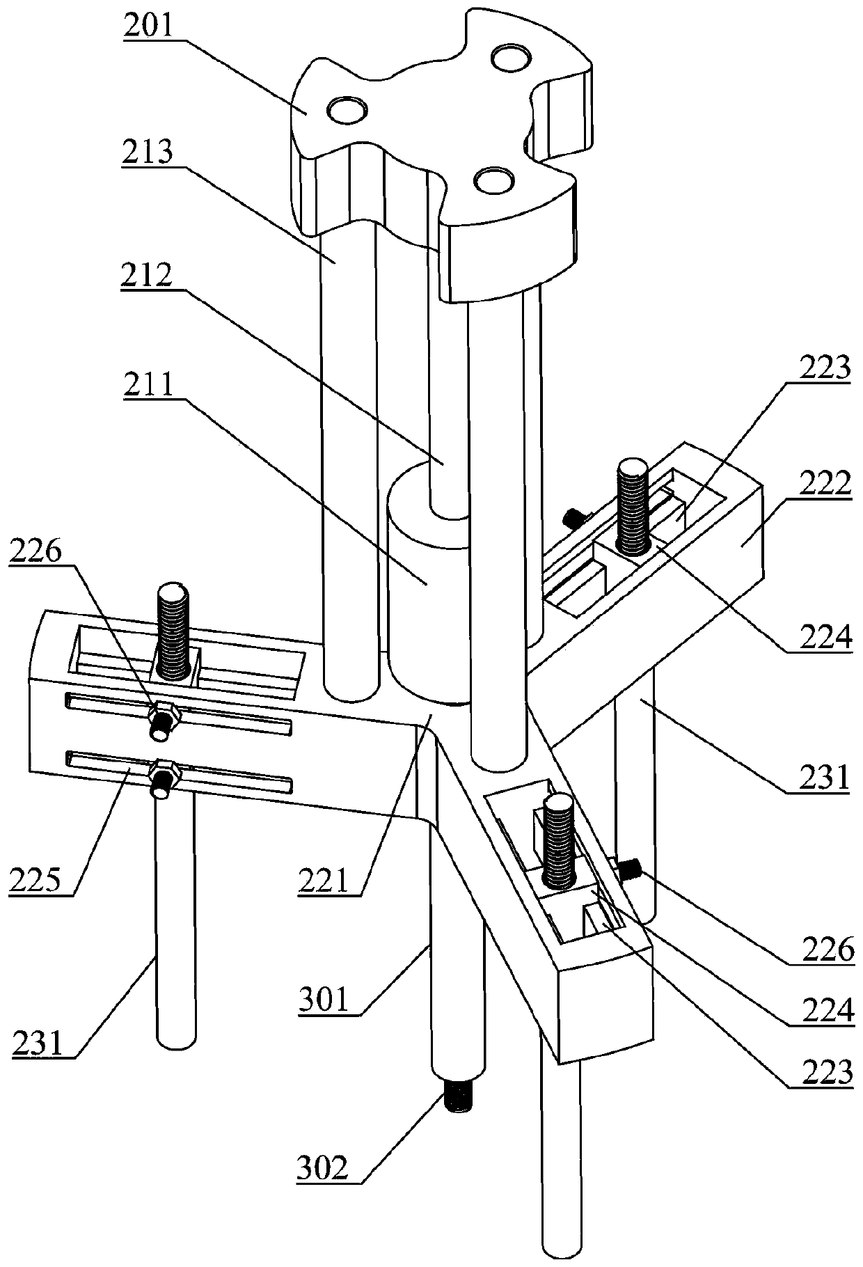
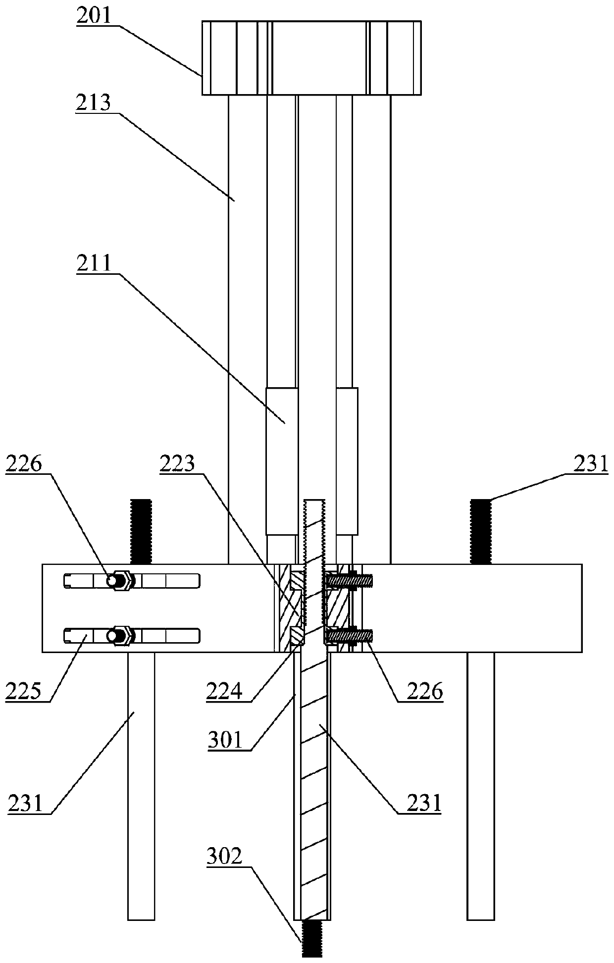
[0039] Such as figure 1 and figure 2 As shown, an electric pin puller provided by an embodiment of the present invention includes an electric drive device (not shown in ...


PUM


Abstract

The invention relates to the technical field of machining equipment, in particular to an electric pin puller. The electric pin puller comprises a collision block guide rod, a collision block, a pin pulling rod and an electric driving device, wherein a stopper is arranged at the upper end of the collision block guide rod, and a support block is arranged at the lower end; the collision block can movably sleeve the collision block guide rod, and is positioned between the stopper and the support block; the upper end of the pin pulling rod is connected with the support block, and a connecting headfor pin pulling is arranged at the lower end; and the electric driving device is arranged on the support block, and drives the collision block to collide with the stopper in the axial direction of thecollision block guide rod. The electric pin puller uses the electric driving device for continuously driving the collision block to move to realize pin pulling, is simple in operation and safe and controllable in working process, and can reduce the labor cost.

Description

technical field [0001] The invention relates to the technical field of machining equipment, in particular to an electric pin puller. Background technique [0002] The use of pins (locking pins, positioning pins, etc.) for fastening and positioning is a common form in mechanical equipment. Since the pin is relatively stable after installation, it is usually time-consuming and labor-intensive to remove it. Existing pin pullers usually use manual knocking or rotation to pull pins, which is complicated to operate, low in efficiency, high in labor costs, and the stability of the pin pulling process is poor, the power energy is uncontrollable, and the risk factor is also high . Contents of the invention [0003] (1) Technical problems to be solved [0004] The technical problem to be solved by the present invention is to solve the problems of difficult operation, poor stability and uncontrollable power energy during the pin pulling process of the existing pin pulling device. ...

Claims


Application Information

Patent Timeline
Patent Type & Authority Patents(China)
IPC IPC(8): B25B27/02
CPCB25B27/023
Inventor 田智立陈磊张涛王国勇魏洪峰夏雅男李卓达辛颖
Owner AEROSPACE INST OF ADVANCED MATERIALS & PROCESSING TECH
Features
  • R&D
  • Intellectual Property
  • Life Sciences
  • Materials
  • Tech Scout
  • Unparalleled Data Quality
  • Higher Quality Content
  • 60% Fewer Hallucinations
Learn More