Cloth supply device

A technology for supplying devices and fabrics, which can be applied to cloth feeding mechanisms, textiles, papermaking, and sewing equipment, etc., and can solve the problems of reduced productivity of clothing materials

Pending Publication Date: 2018-08-28
JUKI CORP
View PDF11 Cites 3 Cited by
  • Summary
  • Abstract
  • Description
  • Claims
  • Application Information

AI Technical Summary

Problems solved by technology

When the cloth supplied from the cloth supply device is conveyed to the sewing machine by the cloth conveying device, if the cloth

Method used


Image

  • Cloth supply device
  • Cloth supply device
  • Cloth supply device

Examples


Embodiment Construction

[0033] Hereinafter, embodiments according to the present invention will be described with reference to the drawings, but the present invention is not limited thereto. The constituent elements of the embodiments described below can be appropriately combined. In addition, some constituent elements may not be used.

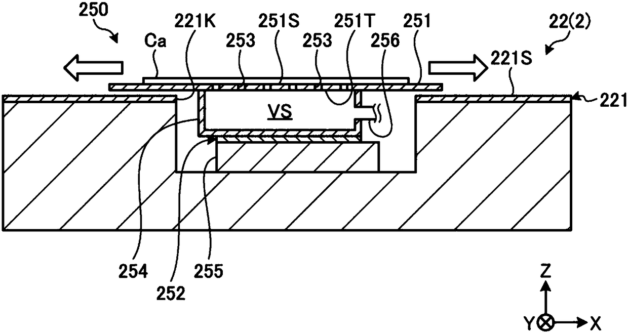
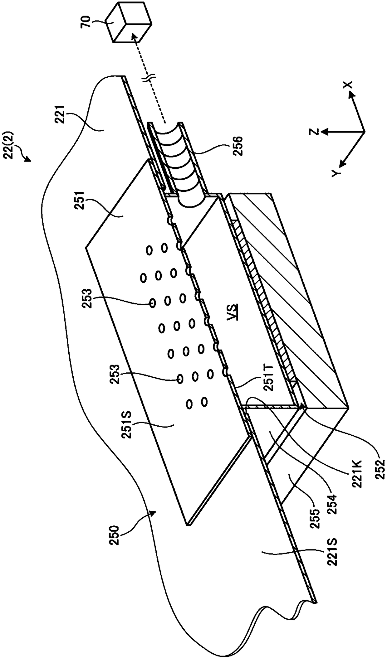
[0034] In the following description, an XYZ rectangular coordinate system is set, and the positional relationship of each part is demonstrated with reference to this XYZ rectangular coordinate system. Let the direction parallel to the X-axis in the predetermined plane be the X-axis direction, let the direction parallel to the Y-axis perpendicular to the X-axis be the Y-axis direction in the predetermined plane, and let the Z-axis perpendicular to the predetermined plane be The parallel direction is defined as the Z-axis direction. In addition, let the rotation direction or the tilt direction around the X axis be the θX direction, let the rotation direction or the t...


PUM


Abstract

The present invention provides a cloth supply device, capable of smoothly conveying cloth to a cloth conveying device. The cloth supply device includes a plate member and a support device, wherein theplate member has an upper surface that sets the cloth and a lower surface that faces the opposite direction of the upper surface, and holes penetrating the upper surface and the lower surface; the support device can support the plate member at a position opposite to a suction surface of the cloth conveying device; and the cloth conveying device vacuum-holds the cloth and conveys the cloth to a sewing machine.

Description

technical field [0001] The invention relates to a cloth supply device. Background technique [0002] In the manufacturing process of clothing materials, the sewing machines disclosed in Patent Document 1 and Patent Document 2 are used. [0003] Patent Document 1: Japanese Patent Laid-Open No. 2016-131614 [0004] Patent Document 2: Japanese Patent Laid-Open No. 2016-131632 [0005] The cloth is supplied from the cloth supply device to the sewing machine. When the cloth supplied from the cloth supply device is conveyed to the sewing machine by the cloth conveying device, if the cloth cannot be smoothly conveyed from the cloth supply device to the cloth conveying device, the productivity of clothing may decrease. Contents of the invention [0006] An object of an aspect of the present invention is to provide a cloth supply device capable of smoothly conveying cloth to a cloth conveying device. [0007] According to an aspect of the present invention, there is provided a ...

Claims


Application Information

Patent Timeline
IPC IPC(8): D05B33/00D05B35/00
CPCD05B33/00D05B35/00D05D2207/04
Inventor 朝见健
Owner JUKI CORP
Why Eureka
Try Eureka