Self-locking mechanism under resistance and hand rocking device

A self-locking and blocking technology, applied in the field of clothes dryers, can solve the problems of wire ropes being easily broken, affecting service life, and wire rope knotting, etc., to avoid repeated folding of wire ropes, prolong service life, and prevent reverse winding.

Pending Publication Date: 2018-08-28
GUANGDONG HOTATA TECH GRP
View PDF0 Cites 4 Cited by
  • Summary
  • Abstract
  • Description
  • Claims
  • Application Information

AI Technical Summary

Problems solved by technology

[0002] Various types of hand cranks currently on the market, in the process of controlling the lifting of the drying rod, if the drying rod is blocked, the hand crank can still rotate, and the possible consequence is that the hand crank idling causes the wire rope wrapped on the I-shaped wheel It is easy to continue winding in the state of no stress stretching, and it is easy to knot the wire rope
At the same time, for various types of hand cranks currently on the market, the wire rope wound on the I-shaped wheel will be wound in the opposite direction when it is exhausted. If the wire rope is often wound forward and then reversed, the wire rope is easy to be broken. , affecting the service life

Method used


Image

  • Self-locking mechanism under resistance and hand rocking device
  • Self-locking mechanism under resistance and hand rocking device
  • Self-locking mechanism under resistance and hand rocking device

Examples


Embodiment 1

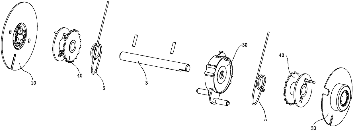
[0034] see Figure 1-5 , the resistance self-locking mechanism shown in the preferred embodiment of the present invention is set on the transmission shaft 3 of the hand crank, including the rear self-locking spring cup assembly 10, the front self-locking spring cup assembly 20, and the resistance self-locking assembly 30 And two spools 40 installed on both sides of the self-locking assembly 30 when blocked.

[0035] The rear self-locking spring cup assembly 10 and the front self-locking spring cup assembly 20 are mounted on both ends of the blocked self-locking mechanism in one-to-one correspondence. Any self-locking spring cup assembly (rear self-locking spring cup assembly 10 or front self-locking spring cup assembly 20) cooperates with adjacent I-shaped wheels 40 to realize self-locking. The structure of the rear self-locking spring cup assembly 10 is basically the same as that of the front self-locking spring cup assembly 20, the only difference being that the front self-...

Embodiment 2

[0048] see Figure 6-9 , the present invention also discloses a hand crank 101, which includes a housing 2, a transmission shaft 3, a crank handle 4, and a self-locking mechanism in case of resistance. The locking mechanisms are the same, and will not be described one by one in this embodiment.

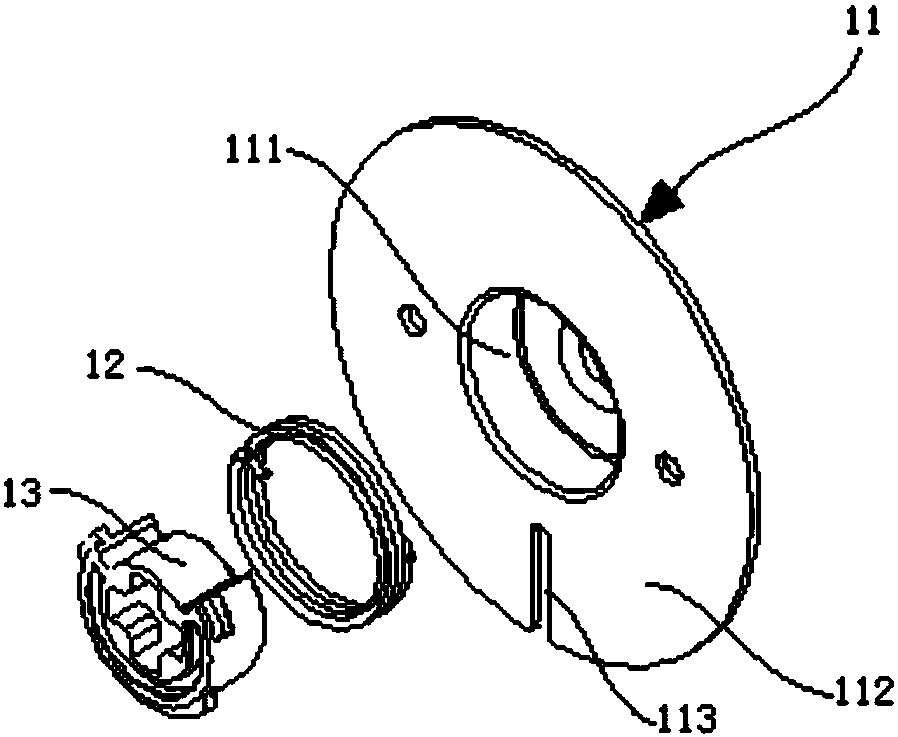
[0049] The housing 2 has an accommodating cavity for installing the blocked self-locking mechanism. The blocked self-locking mechanism is installed in the accommodating cavity of the housing 2 . The spring cup 11 and the anti-loosening cover 31 are fixedly installed in the housing 2 .

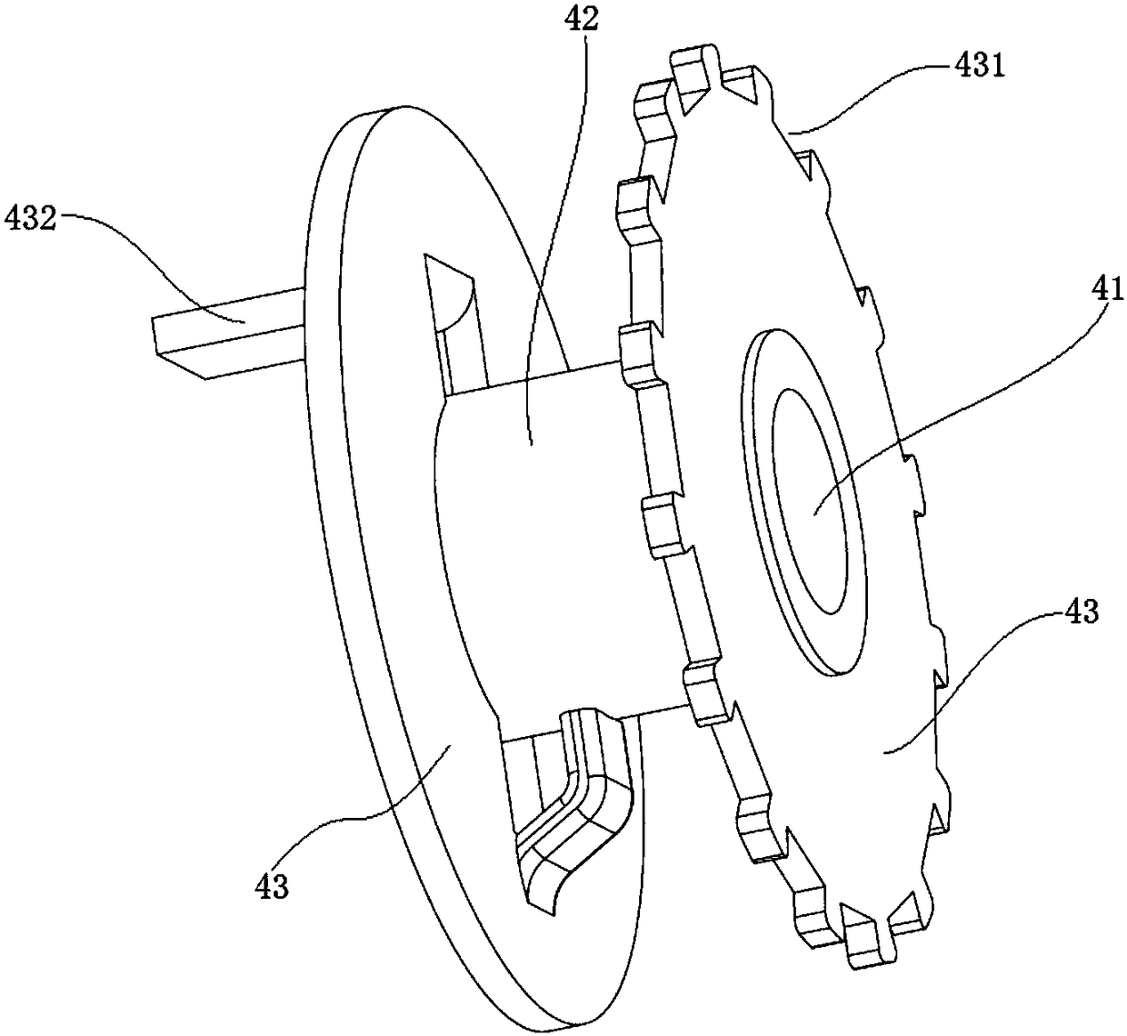
[0050] One end of the transmission shaft 3 passes through the self-locking spring cup assembly, an I-shaped wheel 40, the self-locking assembly 30 in case of resistance, another I-shaped wheel 40, and the rotor 13 of the rear self-locking spring cup assembly 10 in turn. The other end passes through the housing 2 and is connected to the crank handle 4 . The user rotates the crank handle 4 to drive t...


PUM


Abstract

The invention discloses a self-locking mechanism under resistance and a hand rocking device. The self-locking mechanism under resistance comprises a self-locking assembly under resistance, I-shaped wheels coaxially installed on the two sides of the self-locking assembly under resistance and two self-locking spring cup assemblies coaxially installed on the outer sides of the two I-shaped wheels; the self-locking assembly under resistance comprises an anti-disengaging cover, two rotation stopping plates, two line guiding shafts and reset springs installed between the rotation stopping plates andthe anti-disengaging cover; the two rotation stopping plates can both be installed in the anti-disengaging cover in an up-down sliding manner; the top of any rotation stopping plate is convexly provided with a bending head, and the bottom of ant rotation stopping plate is provided with the corresponding line guiding shaft; a steel line rope is wound on any line guiding shaft and then is wound onthe corresponding I-shaped wheel; the periphery of the side, close to the corresponding rotation stopping plate, of each I-shaped wheel is in a concave and convex sawtooth shape; the bending heads areclamped into or disengage from indentations of the corresponding concave and convex sawtooth shapes under the effects of the reset springs or the steel wire rope, and therefore rotation of the I-shaped wheels relative to the rotation stopping plates is limited or released, finally, it is achieved that continuous winding of the steel wire rope is stopped under resistance, and the problems of knotting or repeated winding in the forward and reverse directions are solved.

Description

technical field [0001] This patent relates to the field of clothes dryers, in particular to a blocking self-locking mechanism and a hand crank. Background technique [0002] Various types of hand cranks currently on the market, in the process of controlling the lifting of the drying rod, if the drying rod is blocked, the hand crank can still rotate, and the possible consequence is that the hand crank idling causes the wire rope wrapped on the I-shaped wheel It is easy to continue winding in the state of no stress stretching, and it is easy to knot the wire rope. At the same time, for various types of hand cranks currently on the market, the wire rope wound on the I-shaped wheel will be wound in the opposite direction when it is exhausted. If the wire rope is often wound forward and then reversed, the wire rope is easy to be broken. , affect the service life. Contents of the invention [0003] The purpose of the present invention is to provide a structure with the functio...

Claims


Application Information

Patent Timeline
Patent Type & Authority Applications(China)
IPC IPC(8): F16D59/02B66D1/14B66D1/26B66D1/04B66D1/36D06F57/12
CPCF16D59/02B66D1/04B66D1/14B66D1/26B66D1/36B66D2700/0116D06F57/12
Inventor 沈汉标周道景赖昶靖
Owner GUANGDONG HOTATA TECH GRP
Why Eureka
Try Eureka