Electronic device

A technology for electronic devices and power supply devices, which is applied to coupling devices, two-component connection devices, circuits, etc., can solve the problems of circuit boards that cannot be shunted by signal lines, high component density, and poor heat dissipation effect, so as to reduce manufacturing difficulties. degree, large layout space, the effect of solving short circuit and heat dissipation

Active Publication Date: 2018-08-28
ACER INC
View PDF3 Cites 0 Cited by
  • Summary
  • Abstract
  • Description
  • Claims
  • Application Information

AI Technical Summary

Problems solved by technology

However, the above design cannot shunt the signal lines because the system positive line and the system negative line are limited by the size of the circuit board, so it is easy to cause a short circuit and generate sparks. In addition to safety concerns, it is also due to the The component density is high, which leads to the problem of poor heat dissipation

Method used


Image

  • Electronic device
  • Electronic device
  • Electronic device

Examples


Embodiment Construction

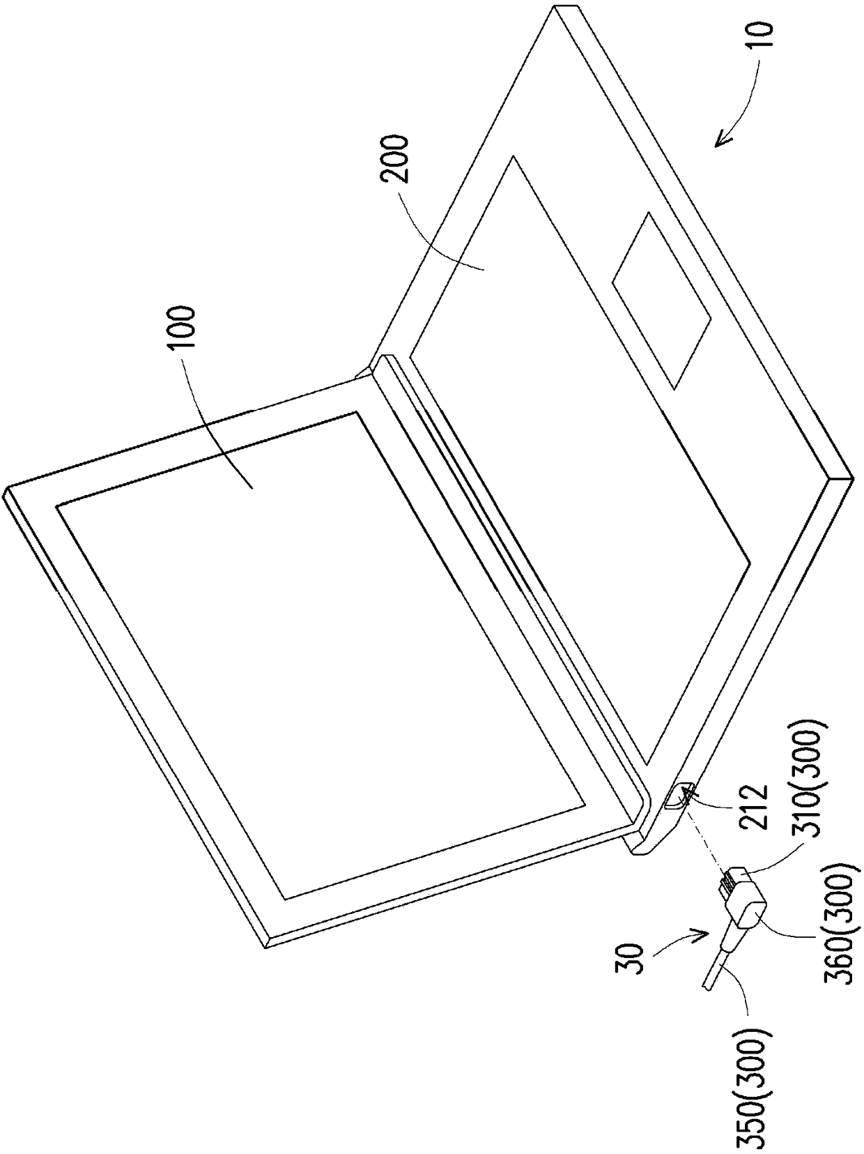
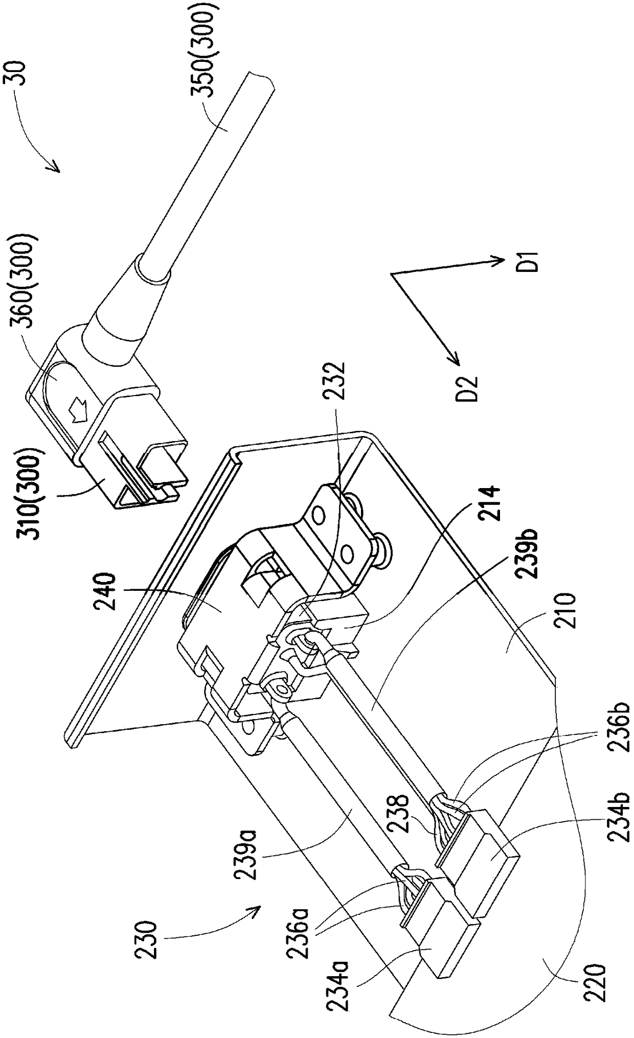
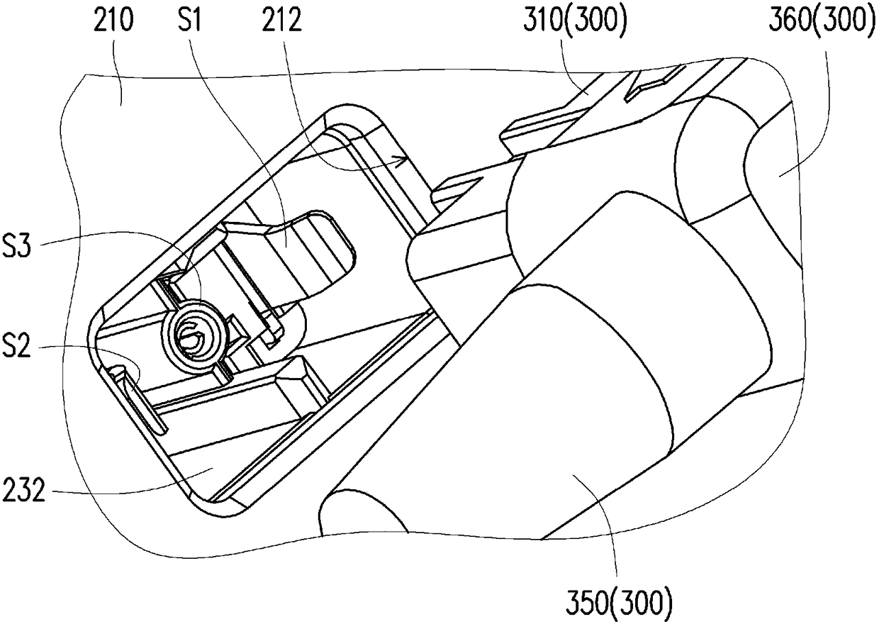
[0063] Figure 1A It is a schematic diagram of an electronic device according to an embodiment of the present invention. Figure 1B for Figure 1A A partially enlarged schematic diagram of the power supply device and the base unit. Figure 1C for Figure 1B The schematic diagram of the power supply device and the base unit from another perspective. figure 2 for Figure 1A A schematic diagram of the system connector. image 3 for Figure 1A The enlarged schematic diagram of the positioning seat of the housing and the system input end of the system connector. Figure 4 for Figure 1A A schematic diagram of the power connector. Figure 5A and Figure 5B respectively Figure 1A Schematic diagram of the power connector in different views. Figure 5C and Figure 5D respectively Figure 1A Schematic diagram of the system connector in different views.

[0064] Please also refer to Figure 1A , Figure 1B , Figure 1C as well as figure 2 , the electronic device 10 of this e...


PUM


Abstract

The invention provides an electronic device, which is electrically connected with a power supply device. The electronic device comprises a display unit and a base unit comprising a housing, a circuitboard and a system connector. The system connector comprises a system input end portion, a system positive electrode end portion, a system negative electrode end portion, a plurality of system positive electrode wires, a plurality of system negative electrode wires and a system detection wire. The system input end portion is arranged corresponding to an opening of the housing. The system positiveelectrode end portion and the system negative electrode end portion are electrically connected with the circuit board. The system positive electrode wires are connected between the system input end portion and the system positive electrode end portion. The system negative electrode wires and the system detection wire are connected between the system input end portion and the system negative electrode end portion. The orthographic projections of the system input end portion, the system positive electrode end portion and the system negative electrode end portion on the housing are not overlapped.

Description

technical field [0001] The invention relates to an electronic device, in particular to an electronic device with high safety. Background technique [0002] At present, most notebook computers are powered by an external power supply device, and a DC-in jack of the notebook computer can receive about 360 watts of power. In order to achieve high power, two DC sockets (DC-in jacks) are usually installed in the notebook computer, so that the electronic device can reach a high power of more than 500 watts. However, since the user must plug in two DC plugs at the same time to use the highest performance, if the user only plugs in the first DC plug and forgets to plug in the second DC plug, the performance of the electronic device will be reduced by half. [0003] Furthermore, since two DC sockets need to be installed, the structure is more complicated, the mold making is difficult, and it is easy to cause the problems of large loss of manufacturing process tolerance, high manufact...

Claims


Application Information

Patent Timeline
Patent Type & Authority Applications(China)
IPC IPC(8): H01R31/06H01R27/02H01R24/28G06F1/16
CPCG06F1/1635H01R24/28H01R27/02H01R31/065H01R2105/00H01R2201/06
Inventor 王友史刘志钧
Owner ACER INC
Why Eureka
Try Eureka