Method for controlling centrifugal pump, and associated pump system

A cooling system, circulation pump technology, applied in general control system, control/regulation system, control using interconnected flow control elements, etc., can solve the problems of high cost, incomplete adaptation to demand, etc.

Active Publication Date: 2018-08-28
WILO SE
View PDF13 Cites 3 Cited by
  • Summary
  • Abstract
  • Description
  • Claims
  • Application Information

AI Technical Summary

Problems solved by technology

These methods are costly in terms of measurement and techni

Method used


Image

  • Method for controlling centrifugal pump, and associated pump system
  • Method for controlling centrifugal pump, and associated pump system
  • Method for controlling centrifugal pump, and associated pump system

Examples


Embodiment Construction

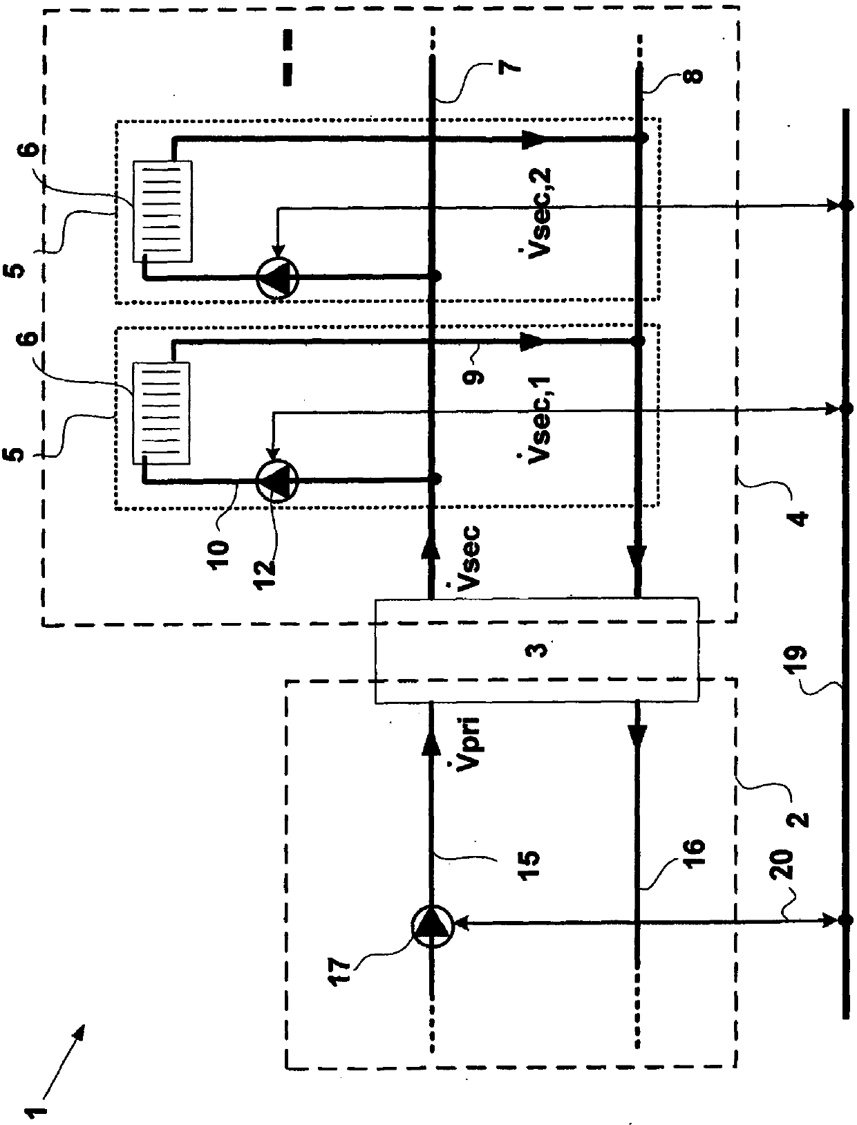
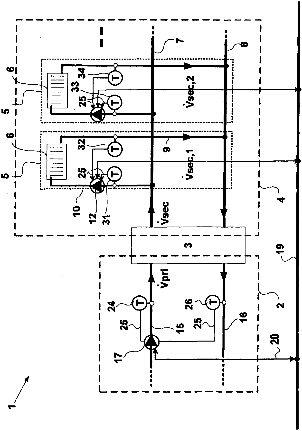
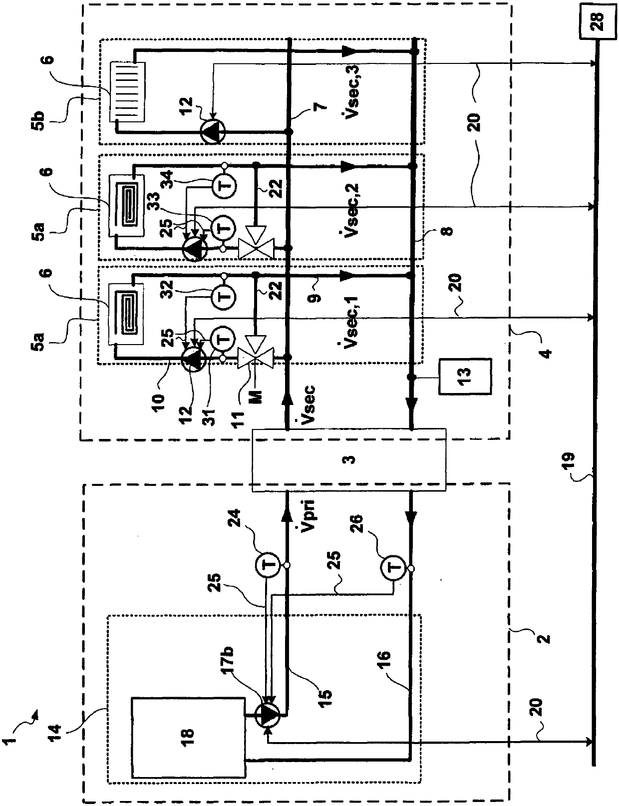
[0045] figure 1 A part of a heating system 1 is shown having a primary circuit 2 and a secondary circuit 4 coupled via a transfer point 3 . The first circulating pump 17 to be controlled conveys heating medium in the primary circuit 2 . Two speed-controlled circulation pumps 12 are located in the secondary circuit 4 , each circulation pump belonging to the consumer circuit 5 and conveying heating medium in the respective consumer circuit 5 . These circulation pumps 12 are connected in parallel in a flow-optimized manner. Therefore, the consumer circuits 5 are also connected in parallel. Each consumer circuit 5 thus forms a partial region of the secondary circuit 4 and comprises a partial flow 10 and a partial return 9 . The local fluid 10 comes from the central secondary fluid line 7 , which is connected to the secondary side of the transfer point 3 . The local return flow 9 flows into the central secondary return line 7 , which is likewise connected to the secondary side...


PUM


Abstract

The invention relates to a method for controlling at least one first circulation pump (17b, 17c) of a heating or cooling system (1) having a primary circuit (2, 2a) and a secondary circuit (4, 30a) coupled therewith at a transfer point (3, 29). The first circulation pump (17, 17b, 17c, 17b') conveys a heating or cooling medium in the primary circuit (2, 2a), and in the second secondary circuit (4,30a), at least one second circulation pump (12, 17d) is located that conveys a heating or cooling medium in at least one partial area of the secondary circuit (4, 30a). The volume flow rate (formulaI) of the first circulation pump (17, 17b, 17c, 17b') is controlled in functional dependence on the volume flow rate (formula II) of the secondary circuit (4, 30) behind the transfer point (3, 29). Inthis way, a demand-based, and thus an energy-efficient control of the primary-side circulation pump is achieved. The invention further relates to a pump system, comprising the at least one first andthe at least one second circulation pump for carrying out the method.

Description

technical field [0001] The invention relates to a method for controlling at least one first circulation pump of a heating or cooling system having a primary circuit and a secondary circuit coupled to the primary circuit at a transfer point, wherein the first circulation pump is in the primary circuit At least one speed-controlled second circulation pump which conveys the heating or cooling medium and conveys the heating or cooling medium in at least one partial region of the secondary circuit is located in the secondary circuit. Background technique [0002] In systems for heating and / or cooling buildings with a liquid heat carrier, the consumers are usually divided in several consumer circuits. For example, such a division can be made by building components or by different consumer types. Different consumer types are, for example, heating elements, or heating and cooling surfaces for floor heating or ceiling heating and cooling. For example, with respect to building compo...

Claims


Application Information

Patent Timeline
IPC IPC(8): F24D19/10F04D15/00
CPCF04D15/0066F24D19/1012F24D2220/0207Y02B30/70F04D13/12G05B13/00G05D11/008G05D11/003G05D7/0133G05B13/041
Inventor 斯蒂芬·施米德
Owner WILO SE
Why Eureka
Try Eureka