Sensor for a magnetic bearing

A magnetic bearing and sensor technology, which is applied in the field of rotating electrical machines and manufacturing such sensor devices, can solve problems such as adjustment errors, sensor signal distortion of sensor rings, etc., and achieve high reliability, high efficiency, and reliable material connection.

Inactive Publication Date: 2018-08-31
SIEMENS AG
View PDF5 Cites 1 Cited by
  • Summary
  • Abstract
  • Description
  • Claims
  • Application Information

AI Technical Summary

Problems solved by technology

Due to high rotational speeds and thermal loads, in the operation of large rotating electrical machines, the sensor ring is lifted during operation and thus the sensor signal is distorted, ie in this way errors in the regulation can then result

Method used


Image

  • Sensor for a magnetic bearing
  • Sensor for a magnetic bearing
  • Sensor for a magnetic bearing

Examples


Embodiment Construction

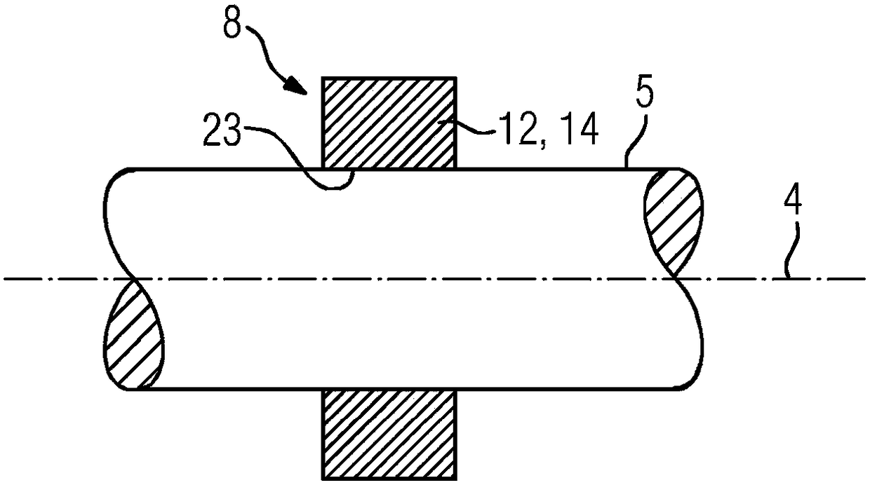
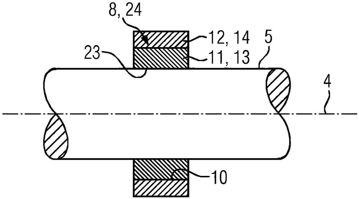
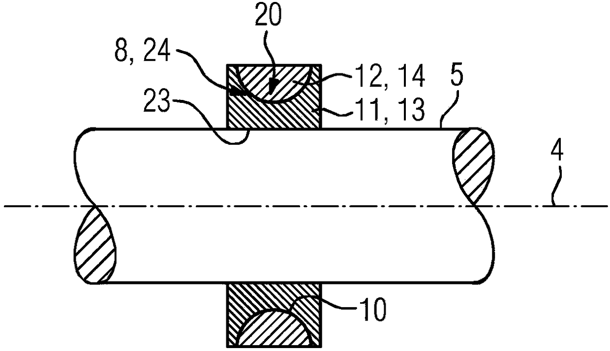
[0037] figure 1 A longitudinal section of the shaft 5 with the sensor ring 8 is shown. Shaft 5 with sensor ring 8 fitted with active magnetic bearings for rotors with demanding rotor dynamics operating on rotating electrical machines with a rotational speed of at least 1000 rpm and a power of at least 1 MW appears.

[0038]In the case of a magnetic bearing of the shaft 5 , the position of the shaft 5 is detected, wherein a magnetic force is exerted on the shaft 5 such that deflection of the shaft 5 is minimized in the magnetic bearing. The input parameter for this adjustment is the position of the shaft 5 , which is measured at a plurality of preferably uniformly distributed positions with movement sensors, for example eddy current sensors. The quality of the measurement signal directly and decisively influences the quality of the control process and the performance of the magnetic bearing. In this case, the sensor ring 8 is used in the sensor arrangement as a sensor target...


PUM


Abstract

The invention relates to a sensor apparatus (15) for a magnetic bearing apparatus (6), having a motion sensor (7) and a sensor ring (8) which has the shape of a hollow cylinder and is intended to be connected to a shaft (5) of an electrical rotating machine (1) in a force-fitting manner, wherein the motion sensor (7) is separated from the sensor ring (8) by an air gap (9). In order to achieve a greater degree of reliability at high rotation speeds and ratings in comparison to the prior art, the sensor ring (8) has a carrier ring (11) composed of a first material (13) and a sensor target (12) composed of a second material (14).

Description

technical field [0001] The invention relates to a sensor arrangement for a magnetic bearing arrangement comprising a movement sensor and a sensor ring. [0002] Furthermore, the invention relates to a rotating electrical machine having a rotor rotating about an axis of rotation, a stator surrounding the rotor and at least one magnetic bearing arrangement with at least one such sensor arrangement. [0003] Furthermore, the invention relates to a method for producing such a sensor arrangement. Background technique [0004] Such sensor arrangements for magnetic bearing arrangements are preferably used in large high-speed rotating electrical machines with a rotational speed of at least 1000 rpm and a power of at least 1 megawatt, since rapidly rotating rotors with strict rotor dynamics are increasingly Supported by active magnetic bearings. [0005] In magnetic bearings, the position of the rotor is detected during rotation and adjusted by exerting a magnetic force on the roto...

Claims


Application Information

Patent Timeline
Patent Type & Authority Applications(China)
IPC IPC(8): G01D5/20G01B7/31
CPCG01D5/202G01D5/2053G01B7/31G01D5/20
Inventor 本杰明·戈特弗里德·乌尔布里希马丁·维沙拉
Owner SIEMENS AG
Why Eureka
Try Eureka