Patient transfer cart with stable braking and good convenience for patient to get out of bed
A patient and trolley technology, applied in hospital beds, medical transportation, transportation and packaging, etc., can solve the problems of patients being easily injured and patient trolleys unable to brake smoothly, so as to avoid tipping or severe jolting, reliable braking, Ease of getting out of bed
- Summary
- Abstract
- Description
- Claims
- Application Information
AI Technical Summary
Problems solved by technology
Method used
Image
Examples
Embodiment 1
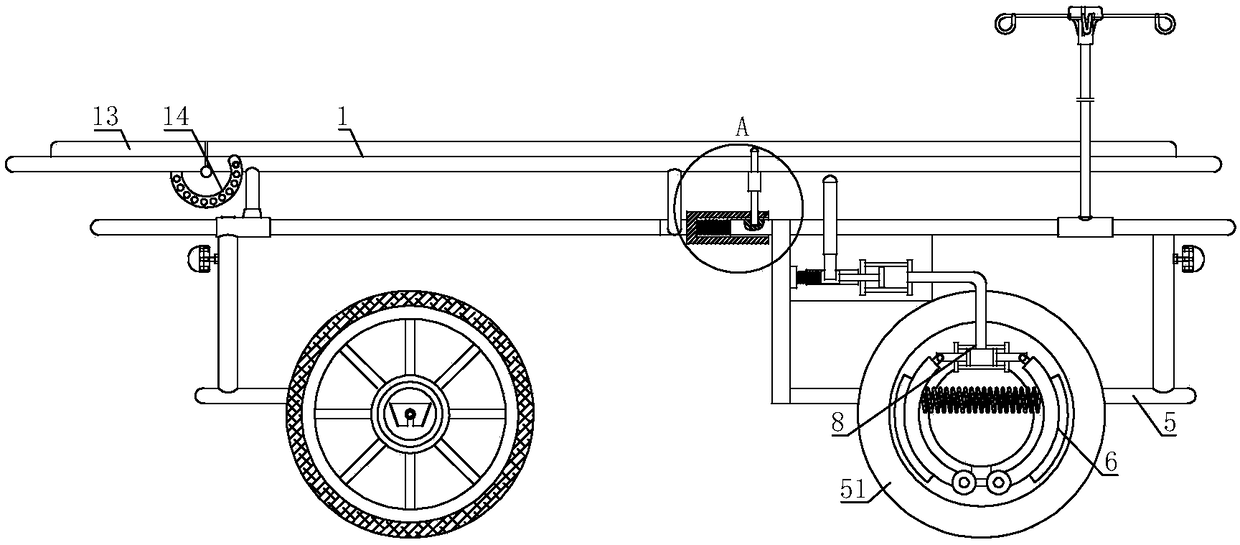
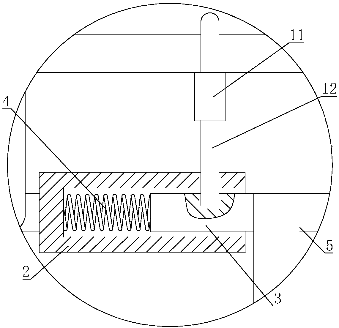
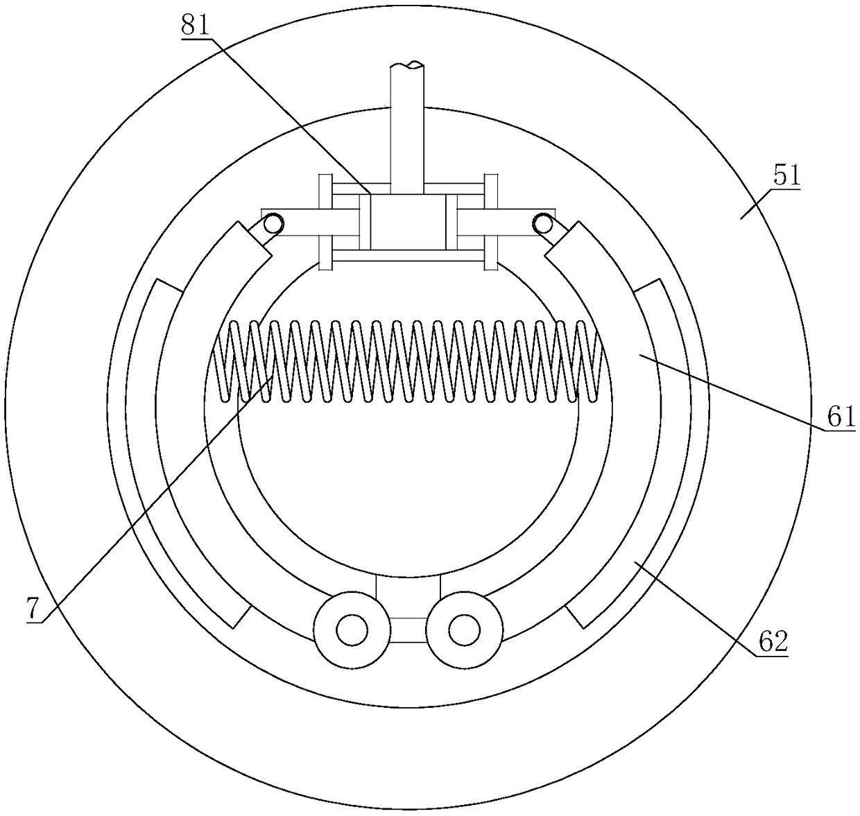
[0028] The patient transfer trolley that brakes smoothly and is convenient for the patient to get out of bed includes a main body 1 of the trolley; a sleeve 2 is connected to the main body 1 of the trolley, and a buffer rod 3 is set inside the sleeve 2, and the buffer rod 3 and the sleeve A buffer spring 4 is connected between them, the other end of the buffer rod 3 is connected with a rear wheel frame 5, the rear wheel frame 5 is connected with a rear wheel 51 through a bearing, and two brake frames 6 are hinged on the rear wheel frame 5, and the two brake frames 6 are hinged. A return spring 7 and a brake hydraulic assembly 8 that pushes the brake frame 6 to tilt are respectively connected between the moving frames 6, and the brake hydraulic assembly 8 is installed on the rear wheel frame 5; one end of the cart body 1 is hinged with a rotating plate 13 , the rotating plate 13 is fixed with an arc frame 14, the arc frame 14 takes the hinge point of the cart main body 1 and the...
Embodiment 2
[0031] On the basis of Embodiment 1, the brake hydraulic assembly 8 includes a two-way hydraulic cylinder 81, which is fixed to the rear wheel frame 5, and the two piston rods of the two-way hydraulic cylinder 81 are respectively hinged to a brake frame 6. The liquid inlet of the hydraulic cylinder 81 is connected with the main hydraulic cylinder 82 through a hydraulic pipe.
[0032] When braking is required, the main hydraulic cylinder 82 is driven to act, the hydraulic oil in the main hydraulic cylinder 82 is pressed into the two-way hydraulic cylinder 83, and the two piston cylinders of the two-way hydraulic cylinder 83 push the brake frame 6 outward, and the brake frame 6, the rear wheel 51 can be braked. Driven by hydraulic pressure, the brake is more reliable and easy to operate. After the braking is completed, the back-moving spring 7 can draw the two brake frames 6 together to release the brake.
Embodiment 3
[0034] On the basis of Embodiment 1 or Embodiment 2, the piston rod of the main hydraulic cylinder 82 is connected with a slider 83, and the rear wheel frame 5 is provided with a chute 52, and the slider 83 is sleeved in the chute 52. A handle 84 is connected to the block 83 , and a release spring 85 is connected between the slide block 83 and the rear wheel frame 5 .
[0035] When braking is required, the hydraulic oil in the main hydraulic cylinder 81 can be pressed into the two-way hydraulic cylinder 82 by pulling the handle 84 to realize the braking operation of the brake frame 6 . After the brake is stopped, the release spring 85 can reversely pull the slide block 83 to ensure that the main hydraulic cylinder 81 and the two-way hydraulic cylinder 82 reset quickly, and ensure that the back-moving spring 7 can pull the two brake frames 6 back to their original positions in time.
PUM
 Abstract
Description
Claims
Application Information
 - R&D
- Intellectual Property
- Life Sciences
- Materials
- Tech Scout
- Unparalleled Data Quality
- Higher Quality Content
- 60% Fewer Hallucinations
Browse by: Latest US Patents, China's latest patents, Technical Efficacy Thesaurus, Application Domain, Technology Topic, Popular Technical Reports.
© 2025 PatSnap. All rights reserved.Legal|Privacy policy|Modern Slavery Act Transparency Statement|Sitemap|About US| Contact US: help@patsnap.com


