
Hanging bracket for power cable construction

A technology of power cables and hangers, which is applied in the field of electric power, can solve problems such as inability to fix, fall of cable reels, hidden dangers, etc., and achieve the effect of preventing damage to cable reels from falling

Inactive Publication Date: 2018-09-04
王柏彰
View PDF0 Cites 0 Cited by
  • Summary
  • Abstract
  • Description
  • Claims
  • Application Information

AI Technical Summary

Problems solved by technology

[0004] In order to solve the above problems, the present invention provides a hanger for power cable construction, which can solve the problems of heavy labor intensity in the lifting and transportation of cable reels, the need for manual assistance to fix the cable reels, and the need for different types of cable reels. Different methods of fixed lifting are required, the cable reel cannot be fixed according to the shape and structure of the cable reel, there is a hidden danger of falling during the lifting of the cable reel, and it is impossible to rotate it during the lifting of the cable rack; Realize the functions of all-round support for different types of cable reels and rotation of the hoisted cable reels, with low labor intensity, automatic fixing of cable reels, fixed lifting for different types of cable reels, It can be fixed according to the shape and structure of the cable reel, there is no hidden danger of falling during the lifting of the cable reel, and it can be rotated during the lifting of the cable rack, etc.

Method used


Image

  • Hanging bracket for power cable construction
  • Hanging bracket for power cable construction
  • Hanging bracket for power cable construction

Examples


Embodiment Construction

[0026] In order to make the technical means, creative features, goals and effects achieved by the present invention easy to understand, the present invention will be further described below in conjunction with specific illustrations. It should be noted that, in the case of no conflict, the embodiments in the present application and the features in the embodiments can be combined with each other.

[0027] Such as Figure 6 As shown, the cable reel is a disc-shaped structure, the inner wall of the cable reel is a coil shaft, angle steel is installed at the front and back of the cable reel, and the central steel frame in the middle of the angle steel is circular.

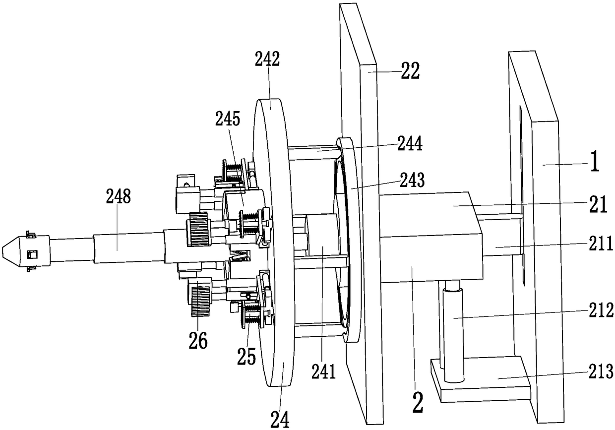
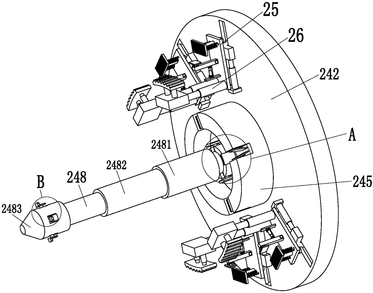
[0028] Such as Figure 1 to Figure 5 As shown, a hanger for power cable construction includes a support side plate 1 and a positioning device 2, a chute is provided on the left side of the support side plate 1, and the positioning device 2 is installed in the middle of the support side plate 1 on the left side.

[00...


PUM


Abstract

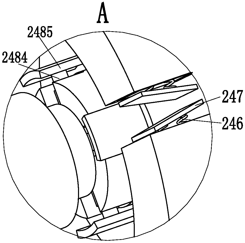
The invention relates to a hanging bracket for power cable construction. The hanging bracket comprises a supporting side plate and a positioning device, wherein a left side face of the supporting sideplate is provided with a sliding groove; the positioning device is mounted on the left side face of the middle part of the supporting side plate; the positioning device comprises a positioning telescoping mechanism, a positioning supporting plate, a rotary mechanism, a side face supporting mechanism and an inner supporting mechanism; the side face supporting mechanism comprises a side face sliding frame, a side face connecting plate, a side face position push rod, a sliding column, a side face spring and a side face clamping plate. According to the hanging bracket provided by the invention, the difficulties that the labor strength is great, cable reels are fixed with the need of artificial assistance, the cable reels with different types need to be fixed and hung by different manners, thecable reels cannot be fixed aiming at the appearance structure of the cable reels, the cable reels have the hidden dangers of falling off in a cable reel hanging process when the existing cable reelsare hoisted, and a cable rack cannot rotates in a cable rack hoisting process and the like are overcome.

Description

technical field [0001] The invention relates to the field of electric power technology, in particular to a hanger for power cable construction. Background technique [0002] The cable reel is a reel with the function of winding wires and cables. The large cable reel is basically a wooden reel. Large cables are widely used in oil fields, mines, construction, machinery manufacturing units, scientific research units and many other industries. Composed of steel frame and wooden structure, the most common cable reel on the market is a steel frame composed of angle steel. The side of the cable reel and the position of the coil axis are all installed wooden boards. The middle part of the steel frame is the center and the steel frame is a circular structure. , to facilitate the extraction and rewinding of the cable after the cable reel is supported. Figure 6 As shown, the cable reel is a disc-shaped structure, the inner wall of the cable reel is a coil shaft, angle steel is install...

Claims


Application Information

Patent Timeline
IPC IPC(8): B66C1/22
CPCB66C1/22
Inventor 王柏彰
Owner 王柏彰
Learn More