High-speed rotating shaft automatic brake

An automatic braking and rotating shaft technology, which is applied in the direction of electric components, mechanical energy control, electrical components, etc., can solve the problems of untimely response, misoperation, and rotating shaft braking by operators, so as to avoid human misoperation, high response sensitivity, The effect of facilitating rapid braking

Inactive Publication Date: 2018-09-04
CHENGDU EXPERT OF BATTERY DESIGN TECH CO LTD
View PDF0 Cites 4 Cited by
  • Summary
  • Abstract
  • Description
  • Claims
  • Application Information

AI Technical Summary

Problems solved by technology

[0003] Under normal circumstances, the braking of the rotating shaft is to manually operate the brake mechanism to lock the rotating shaft and stop the rotating shaft. Human operation will cause the operator to respond untimely, and then it is too late to brake the rotating shaft; at the same time, human operation will also cause wrong operation

Method used


Image

  • High-speed rotating shaft automatic brake
  • High-speed rotating shaft automatic brake
  • High-speed rotating shaft automatic brake

Examples


Embodiment Construction

[0024] Below in conjunction with accompanying drawing, the present invention is described in detail.

[0025] In order to make the object, technical solution and advantages of the present invention clearer, the present invention will be further described in detail below in conjunction with the accompanying drawings and embodiments. It should be understood that the specific embodiments described here are only used to explain the present invention, not to limit the present invention.

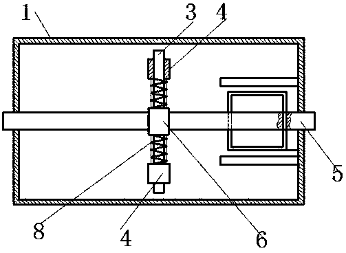
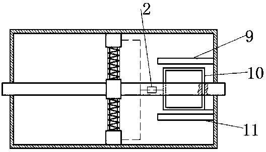
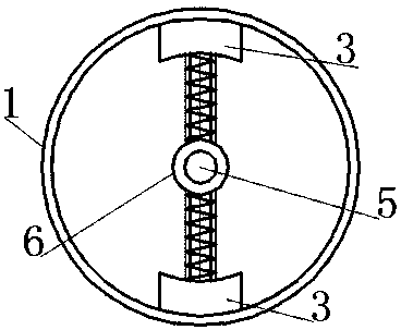
[0026] A high-speed rotating shaft automatic brake, which includes a brake cylinder 1 sleeved on a rotating shaft 5, and relative rotation can occur between the rotating shaft 5 and the brake cylinder 1; a centrifugal mechanism is arranged inside the brake cylinder 1, so The centrifugal mechanism is sleeved on the rotating shaft 5, and the centrifugal mechanism includes a guide rod mounting ring 6, several guide rods 3 and several centrifugal blocks 4; the guide rod mounting ring 6 is fixedly slee...


PUM


Abstract

The invention relates to a high-speed rotating shaft automatic brake, comprising a brake cylinder sleeved on a rotating shaft, wherein relative rotation can occur between the rotating shaft and the brake cylinder; a centrifugal mechanism is arranged in the brake cylinder, and comprises a guide rod mounting ring, a plurality of guide rods and a plurality of centrifugal blocks; the guide rod mounting ring is fixedly sleeved on the rotating shaft, the guide rods are arranged around the guide rod mounting ring by one circle, a centrifugal block and a reset spring are sleeved on each guide rod in asliding way, one end of the reset spring is connected with the side wall of the guide rod mounting rind, and the other end of the reset spring is connected with the bottom of the centrifugal block; the centrifugal blocks are electromagnets; a coil is arranged on the rotating shaft, and is connected with the electromagnets by wires, and a pair of magnetic poles with opposite polarity are arrangedat the coil; the rotating shaft drives the coil to rotate between the magnetic poles, so that the coil cuts a magnetic induction line to generate electric energy to provide power for the electromagnets. The device can enable the rotating shaft to automatically brake under the condition of relatively high rotating speed.

Description

technical field [0001] The invention relates to the field of braking, in particular to an automatic brake for a high-speed rotating shaft. Background technique [0002] During the rotating process of the rotating shaft, the following working conditions exist: when the rotating shaft rotates at a low speed, the rotating shaft rotates normally; when the rotating shaft rotates at a high speed, the rotating shaft stops rotating. [0003] Under normal circumstances, the braking of the rotating shaft is to manually operate the brake mechanism to lock the rotating shaft and stop the rotating shaft. Human operation will cause the operator to respond untimely, and then it is too late to brake the rotating shaft; at the same time, human operation will also cause Misuse. Contents of the invention [0004] The object of the present invention is to provide an automatic brake for a high-speed rotating shaft in view of the above-mentioned problems. The device can automatically brake the...

Claims


Application Information

Patent Timeline
Patent Type & Authority Applications(China)
IPC IPC(8): H02K7/102
CPCH02K7/1023
Inventor 代炎利
Owner CHENGDU EXPERT OF BATTERY DESIGN TECH CO LTD
Why Eureka
Try Eureka