Heating base and cooker utilizing same

A technology for heating bases and cavities, which is applied to cooking utensils, applications, and cooking utensil lids, etc. It can solve problems such as complex component relationships, increased structural complexity, and complex heating base structures, so as to avoid errors and facilitate assembly and maintenance. Effect

Active Publication Date: 2018-09-07
贺运香
View PDF11 Cites 0 Cited by
  • Summary
  • Abstract
  • Description
  • Claims
  • Application Information

AI Technical Summary

Problems solved by technology

[0003] like figure 1 The sectional view of the heating base shown also has a temperature detection component 1 and a micro switch 4. The temperature detection component 1 is installed on a bracket 2, and the bracket 2 is supported by a spring 3. At the same time, the bracket 2 also extends downwards to trigger the micro switch. The cylinder of the switch 4, the microswitch 4 is installed on other structures, and cooperates with the cylinder above. When the temperature detection component 1 and the bracket 2 move down, the microswitch 4 can be triggered. This structure Compared with the existing detection temperature detection structure, it has been greatly improved, but this structure has more failure points. For example, the spring 3 in this technical solution not only needs to support the direct and temperature detection component 1 , and it needs to be placed to be offset. When the position of spring 3 is offset, it will cause the cylinder to fail to trigger with the micro switch 4. If multiple limit structures are added to spring 3, it will generally be in contact with spring 3. Rely on the protruding structure facing the spring 3 in the longitudinal direction, which greatly increases the complexity of each structure; another example is the column extending downward from the bracket 2, the life of the column directly affects whether the micro switch 4 can be triggered; Moreover, the components of the bracket 2, the temperature detection component 1, the spring 3 and the micro switch 4 are complicated in relationship, resulting in a relatively complicated structure of the heating base.

Method used


Image

  • Heating base and cooker utilizing same
  • Heating base and cooker utilizing same
  • Heating base and cooker utilizing same

Examples


Embodiment Construction

[0025] A heating base and a cooker using the heating base of the present invention are described in conjunction with the accompanying drawings.

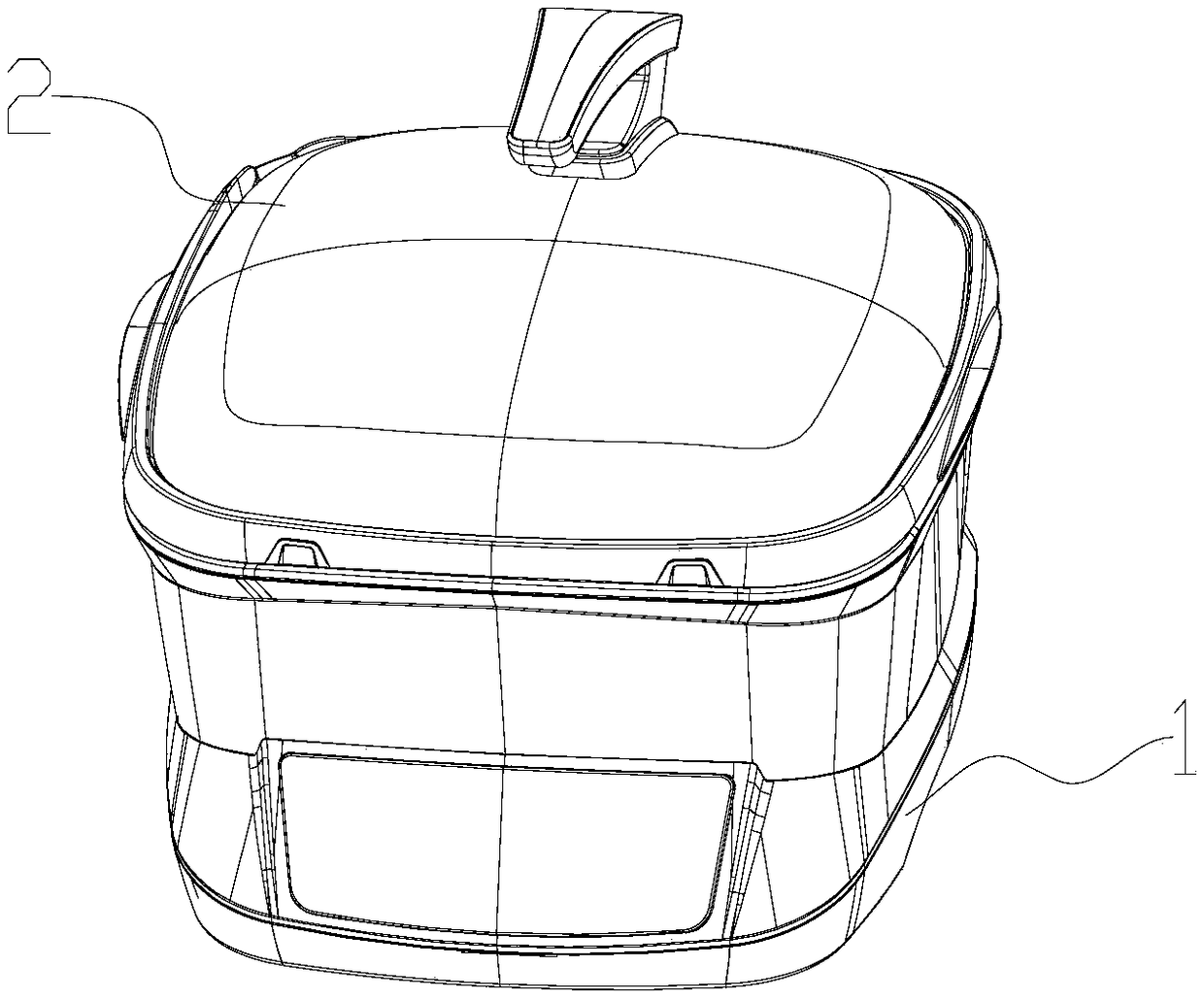
[0026] like Figure 2-8 As shown, a cooker includes a heating base, a cover body 2 and a pot body. The pot body is put into the heating base as a heated object to be heated. In addition, other containers that can be used to hold food can be used as heated objects. Put the object into the heating base for heating, and most of the heating bases in the prior art will monitor the temperature of the heated object and detect whether the heated object is placed. These structures are generally arranged on the heating base.

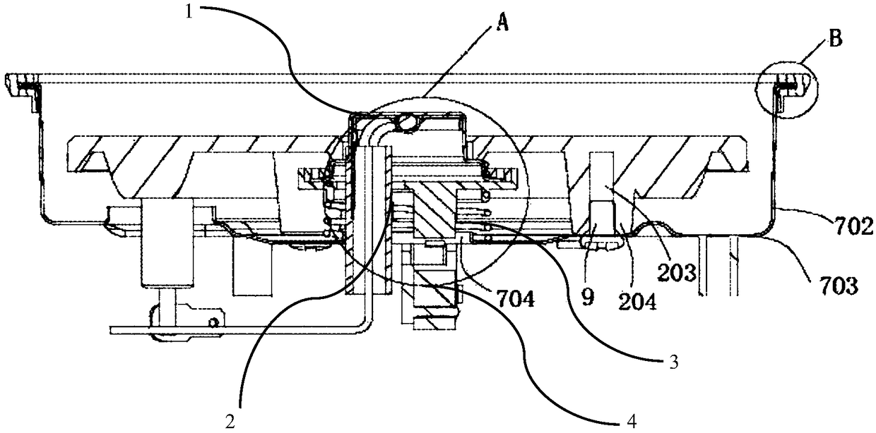
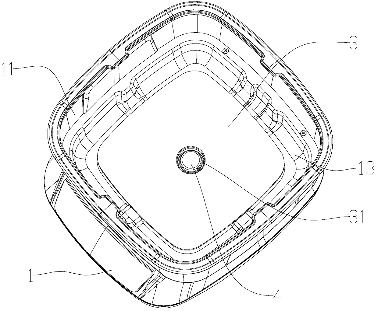
[0027] like Figure 3-4 , 8, the heating base includes the main body 1 of the base, the temperature detection component 4, the bracket 5, the spring 7, the micro switch 6, the heating plate 3 and the trigger plate 8, and the main body 1 is formed with a first cavity 11 and a second A cavity 12, the first cavity 11 is a...


PUM


Abstract

The invention discloses a heating base and a cooker utilizing the same. The heating base comprises a base body, a temperature detecting assembly, a bracket and a microswitch, wherein a first accommodating cavity and a second accommodating cavity are formed in the body, the first accommodating cavity is formed above the second accommodating body, and the first accommodating body and the second accommodating body are separated through a partition board; a first hole penetrated by the temperature detecting assembly is formed in a panel; the first accommodating cavity is used for accommodating a heated object; the bracket and the microswitch are arranged in the second accommodating cavity, the temperature detecting assembly is arranged at the upper part of the bracket in an elastically telescopic manner, and the microswitch is arranged at the lower part of the bracket and is turned on when the heated object props against the temperature detecting assembly. The detection structures of the heating base are improved and are combined into a whole, so that the error rate of the detection structures can be effectively reduced, and the detection structures are convenient to mount and replace.

Description

technical field [0001] The invention relates to the field of heating equipment, in particular to a heating base and a cooker using the base. Background technique [0002] A cooker is a commonly used utensil for cooking food. It has an electric heating base and the object to be heated. In order to monitor the temperature of the object to be heated to make more delicious food, it will be set on the heating base. The temperature detection structure detects the temperature change of the heated object at all times. Similarly, in order to detect whether the heated object is placed on the heating base, a switch for detecting whether the heated object is placed in the heating base is also installed in the heating base. Many cookers in the prior art set these two detection structures separately. [0003] like figure 1 The sectional view of the heating base shown also has a temperature detection component 1 and a micro switch 4. The temperature detection component 1 is installed on ...

Claims


Application Information

Patent Timeline
Patent Type & Authority Applications(China)
IPC IPC(8): A47J36/24A47J27/00A47J36/06
CPCA47J27/002A47J36/06A47J36/24
Inventor 贺运香
Owner 贺运香
Why Eureka
Try Eureka