
Method and system for reducing vehicle parking times at intersections by using planar perception technology

A perception technology, technology of parking times, applied in road vehicle traffic control systems, traffic control systems, instruments, etc., to achieve the effect of reducing parking times

Active Publication Date: 2019-05-14
ANHUI KELI INFORMATION IND +1
View PDF5 Cites 0 Cited by
  • Summary
  • Abstract
  • Description
  • Claims
  • Application Information

AI Technical Summary

Problems solved by technology

[0004] The present invention solves the problem in the prior art that when the current vehicle speed changes due to various conditions, the initial moment of the green light of the traffic signal machine at the downstream intersection cannot be changed following the change of the vehicle speed, and it cannot be changed before the head vehicle of the motor vehicle queue approaches the stop line. , Accurately turn on the green light signal, thereby reducing the technical problem of parking times

Method used


Image

  • Method and system for reducing vehicle parking times at intersections by using planar perception technology
  • Method and system for reducing vehicle parking times at intersections by using planar perception technology
  • Method and system for reducing vehicle parking times at intersections by using planar perception technology

Examples


Embodiment 1

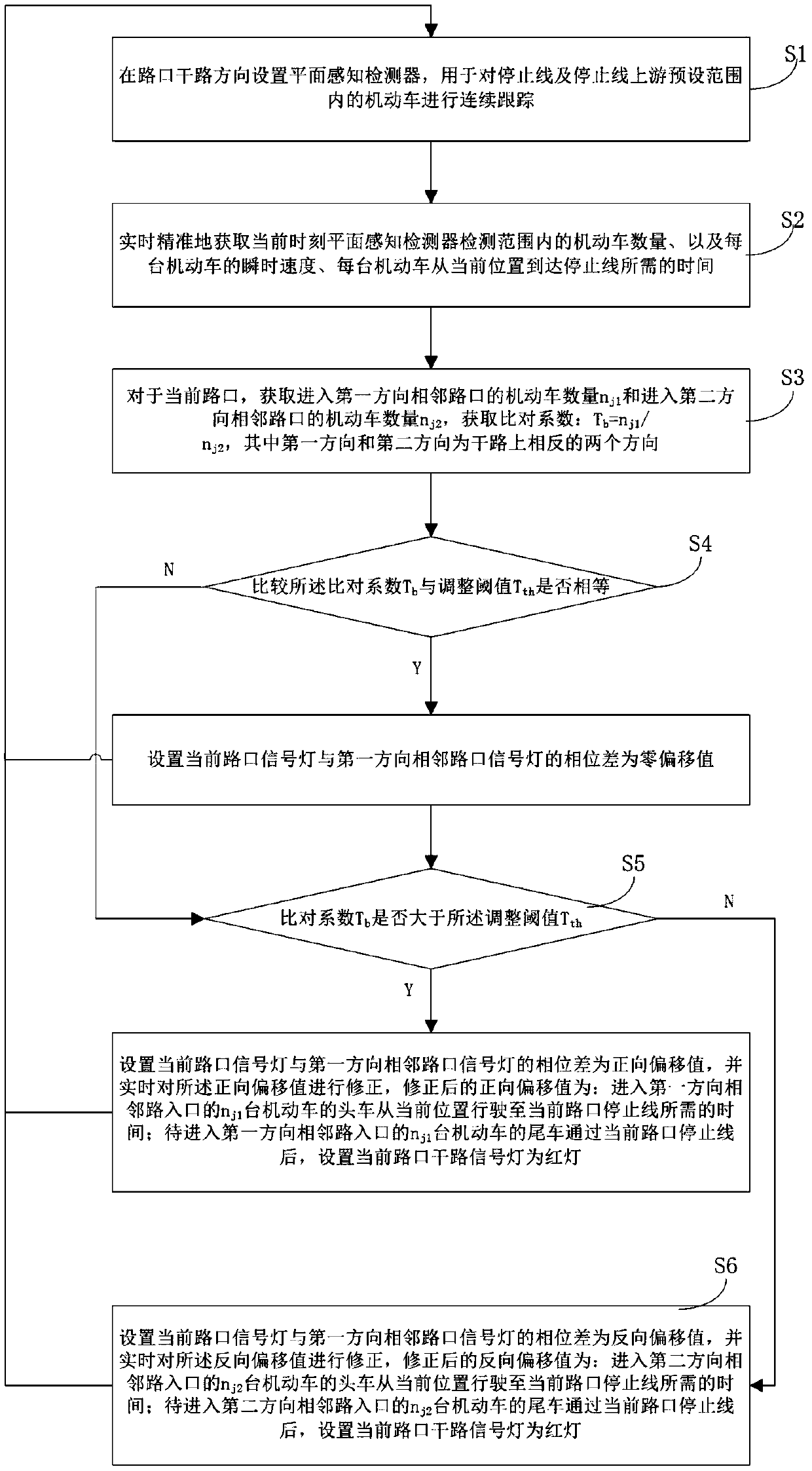
[0035] This embodiment provides a method for reducing the number of motor vehicle parking at intersections by using plane perception technology, such as figure 1 shown, including the following steps:

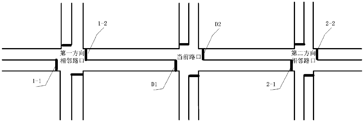
[0036] S1: Set up a plane sensing detector in the direction of the main road at the intersection, which is used to continuously track the motor vehicles within the preset range upstream of the stop line and the stop line; the preset range can cover the distance between the two stop lines at the adjacent intersection all ranges. figure 2 Give a plan view of an intersection.

[0037] S2: Accurately obtain the number of motor vehicles within the detection range of the plane perception detector at the current moment, the instantaneous speed of each motor vehicle, and the time required for each motor vehicle to reach the stop line from the current position in real time.

[0038] S3: For the current intersection, obtain the number n of motor vehicles entering the adjacent intersect...

Embodiment 2

[0045] In this embodiment, on the basis of Embodiment 1, the following improvements are made. In the step S2, the step of accurately obtaining the time required for each motor vehicle to reach the stop line from the current position in real time includes:

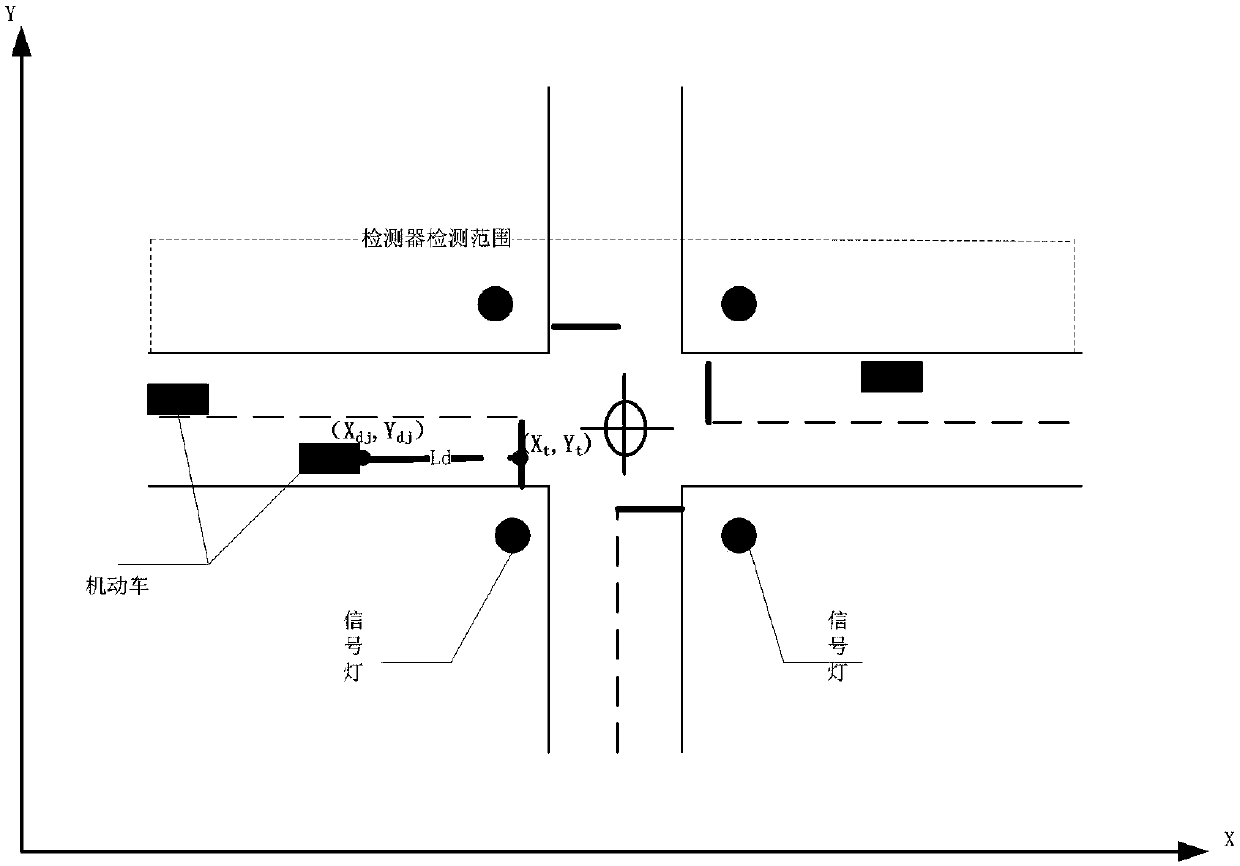
[0046] S21: the installation position coordinate data (X j ,Y j ), the coordinate data of the stop line (X t ,Y t ) marked on the electronic map; it should be noted that, for the installation location and the stop line, both occupy a certain area, so when obtaining the coordinate data, the coordinate data of the center point of the occupied area can be used as Actual coordinate data to use.

[0047] S22: Acquire the actual coordinate data (X dj ,Y dj ), and mark it on the electronic map; the motor vehicle itself has a certain area, so the coordinate data of the motor vehicle is not a point value. In practical application, you can choose the position of the center point of the front end of the motor vehicle The coordin...

Embodiment 3

[0069] In this embodiment, the plane-aware detector adopts a video tracking unit, and further includes the following steps between step S21 and step S22:

[0070] SB1: within the video monitoring range of the video tracking unit, a lane dividing line is set, and a demarcation point F is set on the lane dividing line i , and obtain the actual coordinate data (X f , Y f ) and mark it on the electronic map, and the distance L between every two adjacent demarcation points fi ;Such as Figure 4 Shown is a scheme that uses the endpoints of lane dividers drawn on the road as dividing points. Because the lane dividing line is in the form of a dotted line, there are regulations on the length of the solid line and the distance between the blank lines. Generally, the length of the solid line is 2 meters, and the distance between the blank lines is 4 meters. Therefore, if the two endpoints of the solid line are directly used as demarcation point, it is easy to get the coordinate value...


PUM


Abstract

The present invention provides a method and system for reducing the number of times of parking of motor vehicles at a crossing through adoption of a plane perception technology. The number of the motor vehicles entering at the upstream on each direction at the crossing, the current position of each motor vehicle, the instantaneous speed and the time required from the current position to the stop line can be accurately detected in real time through a plane perception detector, and the phase deviation of a traffic light can be regulated in real time according to the real-time flow changing of two inlets of a subarea trunk road. Besides, according to the scheme of the invention, a monitoring device is not needed, the time for reaching the arrival stop line can be accurately obtained in the different speed of different motor vehicles and different weather conditions. Therefore, according to the scheme of the invention, the method and system for reducing the number of times of parking of motor vehicles at the crossing through adoption of the plane perception technology can accurately obtain the accurate time of each motor vehicle from an upstream crossing outlet to the stop line so as to accurately start traffic signals for the first vehicle of the motor vehicle queue for reaching the stop line and ensure that the number of times of parking is reduced when the motor vehicles pass through the crossing.

Description

technical field [0001] The invention relates to the technical field of intelligent transportation, in particular to a system and method capable of reducing the number of parking times of motor vehicles at intersections by using plane sensing technology. Background technique [0002] With the rapid growth of urban traffic demand, people are using motor vehicles to travel more and more. In order to meet the needs of motor vehicle travel, from the road level, the relevant departments have accelerated the speed of road construction, and from the traffic management level, it has continuously increased. The density of intersections controlled by signal lights, in this way, while regulating the traffic order, also causes motor vehicles to often stop multiple times when passing through these intersections, and the travel time is continuously extended, which brings inconvenience to people's travel. How to reduce the number of times that motor vehicles stop when passing through a plur...

Claims


Application Information

Patent Timeline
Patent Type & Authority Patents(China)
IPC IPC(8): G08G1/08G08G1/081
CPCG08G1/08G08G1/081
Inventor 姜廷顺梁子君宋志洪石勇王家捷陶刚
Owner ANHUI KELI INFORMATION IND
Learn More