Special telescopic handbarrow for installation rails of transformer equipment

A technology for equipment installation and handling tools, applied in the directions of transportation and packaging, manual conveying devices, etc., can solve problems such as difficulty, large manpower and time, and injured personnel, so as to shorten the construction time, reduce the handling time, and improve the work. The effect of efficiency

Pending Publication Date: 2018-09-07
GUANGDONG POWER GRID CO LTD +1
View PDF4 Cites 1 Cited by
  • Summary
  • Abstract
  • Description
  • Claims
  • Application Information

AI Technical Summary

Problems solved by technology

[0002] It is often necessary to add or relocate main transformers and line high-voltage reactors (hereinafter referred to as high-voltage reactors) in substations. Since the weight of the main transformers and high-voltage reactors is as high as 100 to 150 tons, the relocation and installation costs of large cranes are high, and crane installations often require Cooperating with surrounding equipment in case of power outage, the operability is not high in practice. Therefore, manufacturers and construction teams often use hydraulic pumps and rails for relocation and installation.
In this process, the relocation of the track has become a very troublesome problem. Usually, more than 4 sections of the track are required. A single section of track is about 3 to 4 meters long. At least 4 people are required to lift it up. Because the track is heavy and long, it is difficult to move. It is large, consumes a lot of manpower and time, and requires high physical strength and attention of the construction personnel. At the same time, there is a risk of slipping and hurting personnel during long-distance transportation.

Method used


Image

  • Special telescopic handbarrow for installation rails of transformer equipment
  • Special telescopic handbarrow for installation rails of transformer equipment

Examples


Embodiment 1

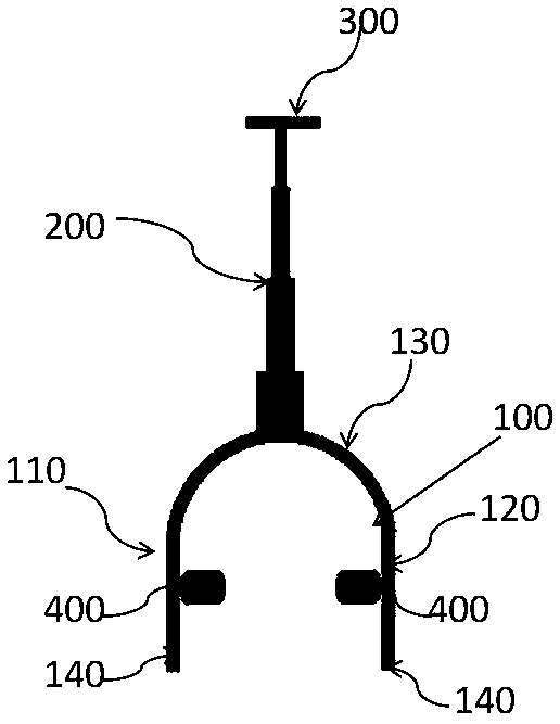
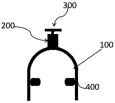
[0021] Such as Figure 1~2 As shown, a special transport tool for the installation track of retractable transformer-like equipment includes a vertical body 100, a first connecting rod 200, and a handle 300. The first connecting rod 200 is connected to the upper end of the vertical body 100, and The lower end is provided with a support point 140 for supporting the ground, and the handle 300 is connected with the first connecting rod 200 .

[0022] Wherein, the first connecting rod 200 is an adjustable and telescopic multi-stage bushing structure, preferably a four-stage bushing in this implementation.

[0023] The inner wall of the X-shaped main body 100 is provided with two pulleys 400, opposite between the two pulleys 400, and the size between the two pulleys 400 is matched with the rail 500, so that the two pulleys 400 can just pass through the rails and will not Slip off the rails.

[0024] Wherein, the X-shaped main body 100 comprises a left support rod 110, a right supp...


PUM


Abstract

The invention provides a special telescopic handbarrow for installation rails of transformer equipment. The special telescopic handbarrow comprises an n-shaped main body, a first connecting rod and ahandle, wherein the first connecting rod is connected to the upper end of the n-shaped main body; support point parts for being supported on the ground are arranged at the lower ends of the n-shaped main body; the handle is connected to the first connecting rod which is of an adjustable telescopic structure; two pulleys are arranged on the inside wall of the n-shaped main body and opposite to eachother; and the distance between the two pulleys is matched with a steel rail, so that the steel rail can exactly pass through the gap between the two pulleys, and the two pulleys cannot slip off thesteel rail. The special telescopic handbarrow for the installation rails of the transformer equipment can be used for easily carrying the steel rail, the carrying time of the steel rail and the project construction time are shortened, the working efficiency is improved, and a carrying person is protected against a body injury risk. In addition, the first connecting rod is telescopic, such that thespecial telescopic handbarrow is convenient to carry, can be used in more situations and is not limited to the space.

Description

technical field [0001] The invention relates to the field of power supply construction operations, and more specifically, to a special transport tool for retractable transformer equipment installation tracks. Background technique [0002] It is often necessary to add or relocate main transformers and line high-voltage reactors (hereinafter referred to as high-voltage reactors) in substations. Since the weight of the main transformers and high-voltage reactors is as high as 100 to 150 tons, the relocation and installation costs of large cranes are high, and crane installations often require In practice, the operability is not high due to the power failure of the surrounding equipment. Therefore, the method often adopted by manufacturers and construction teams is to use hydraulic pumps and rails for relocation and installation. In this process, the relocation of the track has become a very troublesome problem. Usually, more than 4 sections of the track are required. A single s...

Claims


Application Information

Patent Timeline
Patent Type & Authority Applications(China)
IPC IPC(8): B65G7/12
CPCB65G7/12
Inventor 刘晓洲张斌斌胡良山郭伟逢刘欢张焕燊傅龙伟龚演平陈正龙陈慧聪谢树泳刘延伟周俊宏韩金越张健鄢雨侯李佳奇
Owner GUANGDONG POWER GRID CO LTD
Why Eureka
Try Eureka