Shaking table moving device of computerized flat knitting machine

A mobile device, flat knitting machine technology, applied in the directions of knitting, weft knitting, textile and paper making, etc., can solve the problems of waste of resources, not given, increase the input cost of computerized flat knitting machine equipment, etc., to avoid waste of resources , the effect of good versatility

Pending Publication Date: 2018-09-07
常熟市淼泉铸造有限公司
View PDF4 Cites 0 Cited by
  • Summary
  • Abstract
  • Description
  • Claims
  • Application Information

AI Technical Summary

Problems solved by technology

Although the aforementioned patents that are not limited to examples can satisfy the mutual movement between the two needle beds of the computerized flat knitting machine so as to meet the alignment requirements between the transfer needle and the extension needle, there are the following disadvantages: 1. Since the entire shaker assembly is a computerized flat knitting machine structure system, the needle bed body (also called "frame" or "needle bed") is provided with a needle bed (also called "needle board", the same below). Bed", the same below) is set for the carrier, so the reliability of cooperation between the shaker assembly and the needle bed body, the convenience of installation and the convenience of daily maintenance are all important factors that cannot be neglected. However, none of the above-mentioned patents provides necessary technical inspiration; secondly, as known in the industry, there are single-shaker moving devices and double-shaking mobile devices according to different needs, and the single-shaking mobile device is as mentioned above. And the CN203878296U, the double shaker mobile device is as aforementioned CN203270200U, the single shaker mobile device can only deal with the lateral movement of one needle bed, that is, the needle plate, and the double shaker mobile device can simultaneously satisfy the needs of two needle beds, that is, the needle plate. traverse
However, the current situation is that as a manufacturer of shaking table mobile devices, there are usually two different specifications, different structural forms and no universal single-shaking table mobile devices and double-shaking table mobile devices. Therefore, the same computer As far as the flat knitting machine is concerned, when it is necessary to change the single shaker mobile device to a double shaker mobile device or vice versa, it can only be satisfied by adding the corresponding shaker mobile device, thus improving the performance of the computerized flat knitting machine on the one hand. Using the manufacturer's equipment to invest costs, on the other hand, causes waste of resources. This technical problem is also not given the technical enlightenment that can be solved in the aforementioned patents.

Method used


Image

  • Shaking table moving device of computerized flat knitting machine
  • Shaking table moving device of computerized flat knitting machine
  • Shaking table moving device of computerized flat knitting machine

Examples


Embodiment Construction

[0021] In order to be able to understand the technical essence and beneficial effects of the present invention more clearly, the applicant will describe in detail in the form of examples below, but the description of the examples is not a limitation to the solution of the present invention. Anything made according to the concept of the present invention All equivalent transformations that are merely formal rather than substantive should be regarded as the scope of the technical solution of the present invention.

[0022] In the following description, all concepts related to the directionality or orientation of up, down, left, right, front and rear are based on figure 1 The position state shown is for the purpose, so it cannot be understood as a special limitation to the technical solution provided by the present invention.

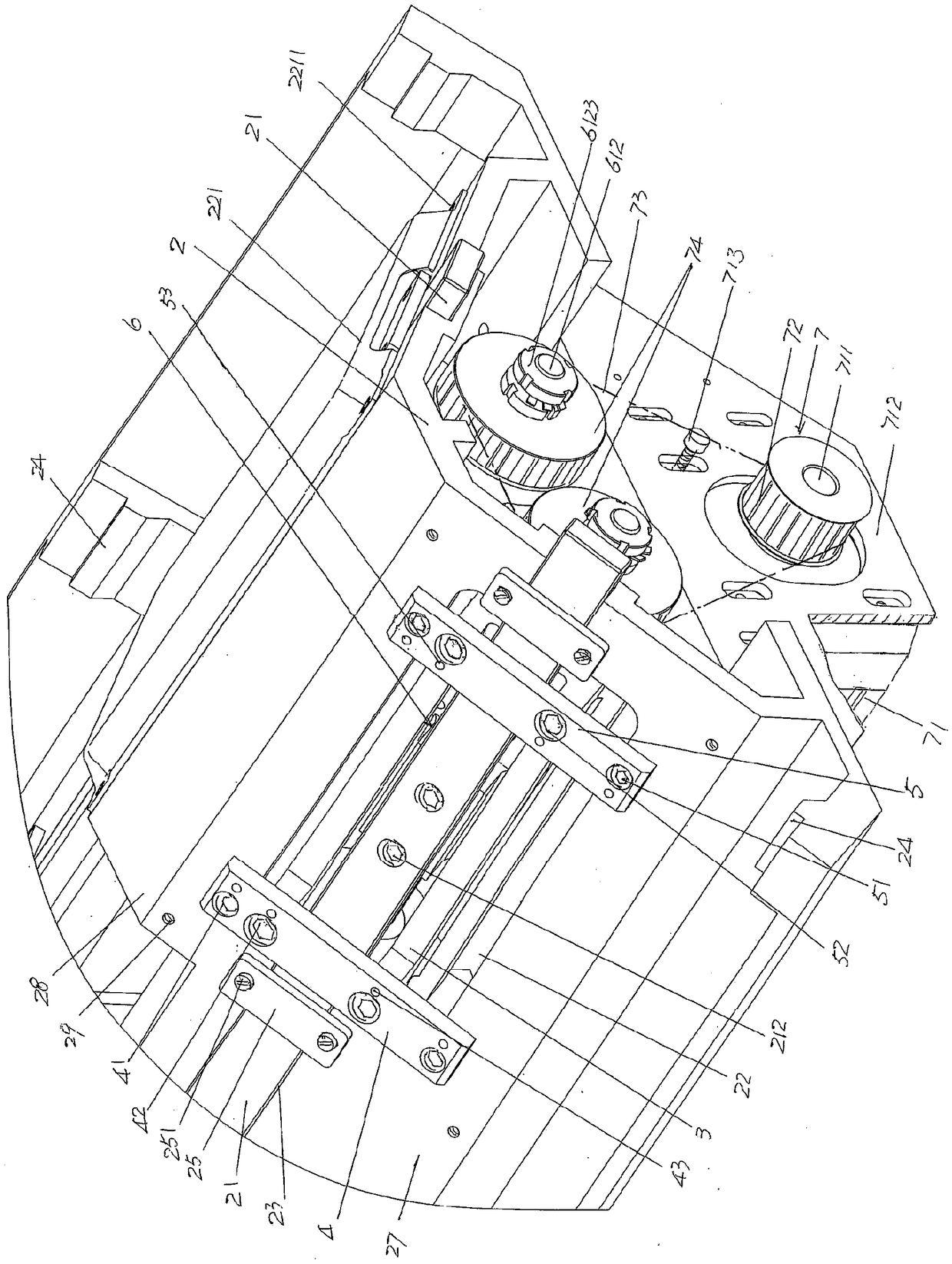
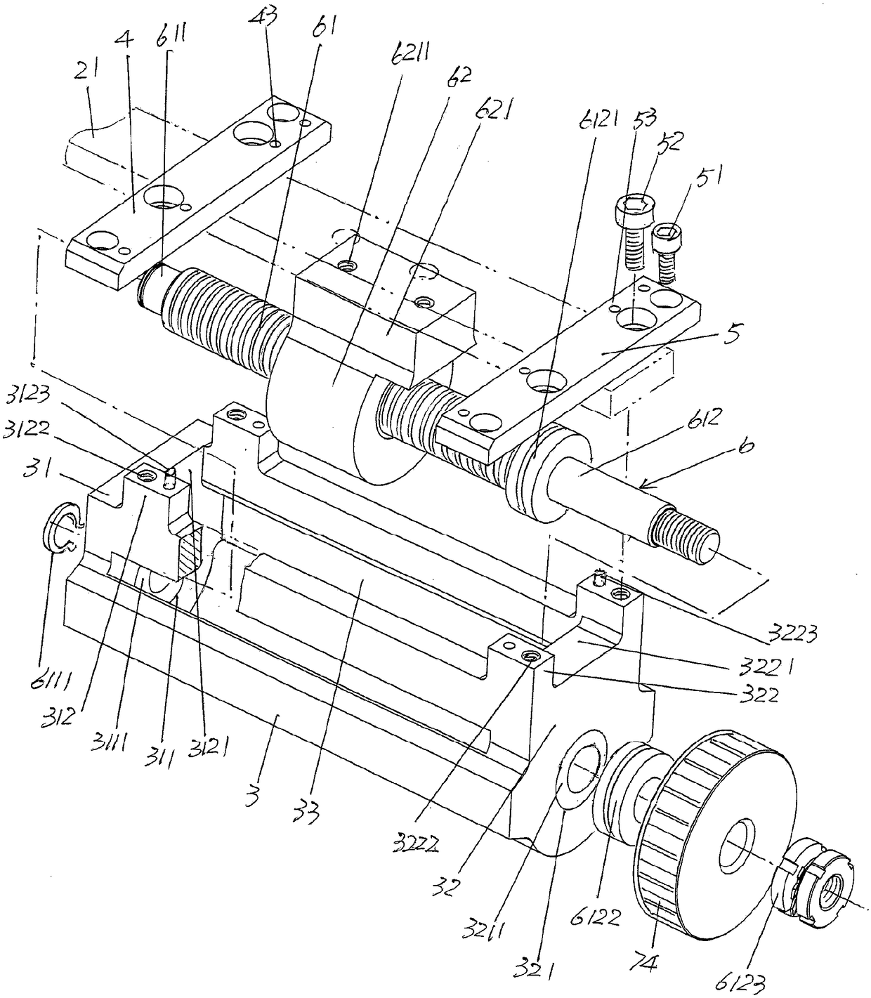
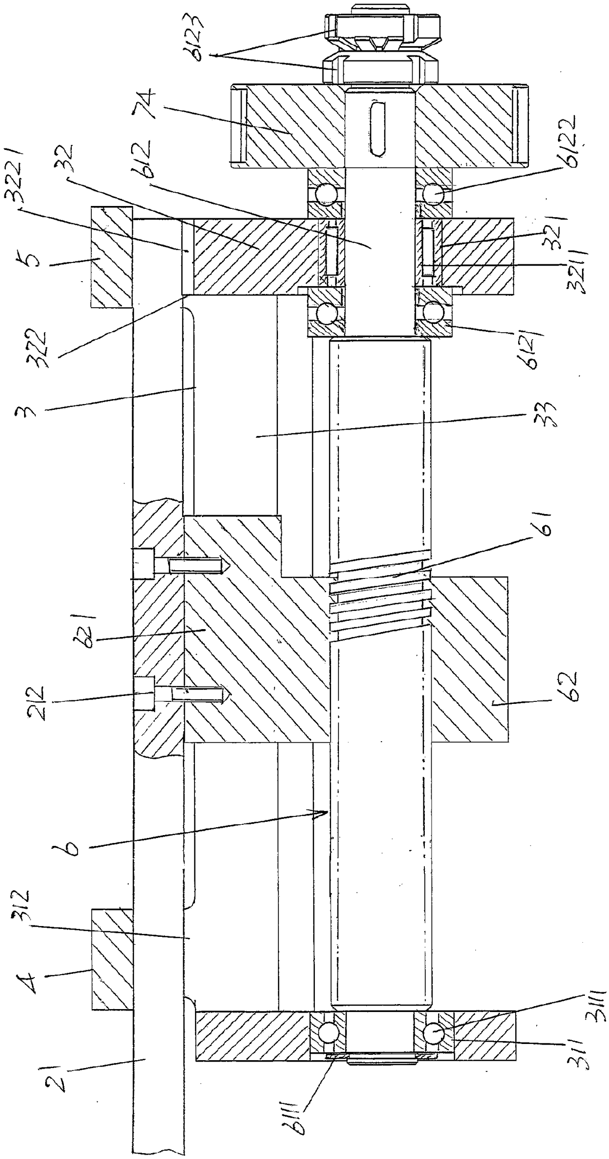
[0023] See figure 1 And combine Figure 4 with Figure 5 , Shows the structural system of the computerized flat knitting machine for sliding support by Figure ...


PUM


Abstract

The invention relates to a shaking table moving device of a computerized flat knitting machine, and belongs to the technical field of computerized flat knitting machines. The computerized flat knitting machine comprises a needle bed body for slidably supporting a needle bed, wherein needle bed connecting guide bars is arranged at the front side and the rear side of the bed body, the right sides ofthe front side and the rear side are respectively provided with abdicated a cavity. The shaking table moving device includes: a shaking table frame, wherein the left end of the shaking table frame isfixed with the left fixing plate of the shaking table frame and the right end of the shaking table frame is fixed with the right fixing plate of the shaking table frame. The left fixing plate and theright fixing plate of the shaking table frame are fixed on one side of the needle bed body, facing the outer side; a guide bar displacement driving mechanism, wherein the mechanism is connected withthe needle bed connecting guide bar at a position corresponding to the abdicated cavity; and a power transmission mechanism, wherein the power transmission mechanism is fixedly connected with the right end of one side of the needle bed body, facing downwards, and is in transmission connection with the guide bar displacement driving mechanism. The matching reliability between the shaking table frame and the needle bed body is reflected; the convenience of connection with the connecting guide bar of the needle bed is realized; the shaking table device is protected; and the universality is good.

Description

Technical field [0001] The invention belongs to the technical field of computerized flat knitting machines, and particularly relates to a shaker moving device of a computerized flat knitting machine. Background technique [0002] The computerized flat knitting machine can automatically complete the normal loop formation, and also automatically complete the loop transfer, so that complex patterns can be knitted. In order to adapt the computerized flat knitting machine to the knitting requirements of different fabric structures, different patterns (patterns), etc., the needle bed needs to be moved laterally, and the lateral movement of the needle bed needs to be guaranteed by a shaker moving device. In addition to the reasonableness of its own structure, the shaker moving device has an impact on the traverse speed and positioning accuracy of the needle bed on the performance of the computerized flat knitting machine and even the knitting quality of the fabric. When the relative po...

Claims


Application Information

Patent Timeline
Patent Type & Authority Applications(China)
IPC IPC(8): D04B15/12
CPCD04B15/12
Inventor 高晓
Owner 常熟市淼泉铸造有限公司
Why Eureka
Try Eureka