Tray

A technology of pallets and bosses, which is applied in the field of stacking and packaging, and can solve the problems of unseen pallet products and unseen products, etc.

Active Publication Date: 2013-03-20
SUZHOU TONGDA MACHINERY
View PDF6 Cites 45 Cited by
  • Summary
  • Abstract
  • Description
  • Claims
  • Application Information

AI Technical Summary

Problems solved by technology

However, there are still shortcomings, because the patent application scheme only constitutes the first supporting seats protruding from the surface of the side and distributed at intervals on the surface of the tray body facing the floor (facing the floor in use), On the surface of the side of the reinforcement bracket facing the tray body and at the position corresponding to the first support seat, there are second support seats distributed at intervals. When the first and second support seats are matched with each other, the tray body is relatively Because the floor is in a vacated state, more precisely, a shovel arm slot for the shovel arm of the forklift is formed between adjacent support seats, so there is not only pickiness in the actual use process, but also the handling of workers Insufficient work intensity
Because, when the side with the forklift slot on the pallet is facing away from the ground, the forklift cannot function; The items on the pallet body are removed from the pallet body alone, and the items can only be transferred from one place to another together with the pallet, and if the items are to be removed from the pallet body, it can only be done manually by the loading and unloading workers. Not only is the efficiency low, but also requires a lot of manpower, and the labor intensity of the workers is high
[0004] The applicant has carried out a relatively comprehensive search, but no technical revelation that can eliminate the aforementioned shortcomings has been found in the published Chinese and foreign patent documents and non-patent documents. And neither heard nor witnessed the successful reports and actual pallet products in the industry

Method used


Image

  • Tray
  • Tray

Examples


Embodiment Construction

[0022] In order to enable the examiners of the patent office, especially the public, to understand the technical essence and beneficial effects of the present invention more clearly, the applicant will describe in detail the following in the form of examples, but none of the descriptions to the examples is an explanation of the solutions of the present invention. Any equivalent transformation made according to the concept of the present invention which is merely formal but not substantive shall be regarded as the scope of the technical solution of the present invention.

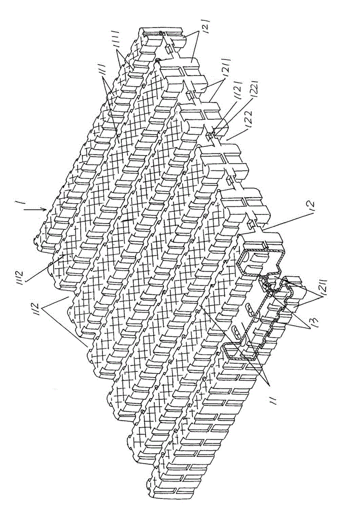
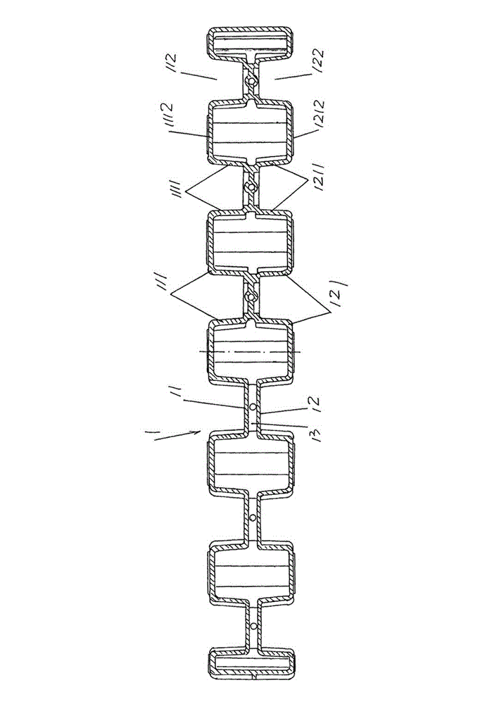
[0023] Please see figure 1 and figure 2 , the given tray body 1 is composed of the first and second disc petals 11 and 12 which have the same structure obtained by plastic blowing and are integrated with each other in the shape of a cube (but can also be a cuboid). A first object-bearing boss 111 extending from one side of the first disk flap 11 to the other side and protruding from the surface of the first...


PUM


Abstract

The invention relates to a tray, which belongs to the technical field of stacking and packaging materials. The tray comprises a rectangular or square tray body which is obtained by blowing and is formed in a manner that first and second tray sections with the same structures are connected with each other. The tray is characterized in that: first carrying bosses which are extended to the other side from one side of the first tray section and are protruded on the surface of the first tray section are formed at intervals on the first tray section; and a first shovel arm slot is formed between the adjacent first carrying bosses; second carrying bosses which are extended to the other side from one side of the second tray section and are protruded on the surface of the second tray section are formed at intervals on the second tray section; and a second shovel arm slot is formed between the adjacent second carrying bosses; the first and second carrying bosses are corresponding to each other; and the first and second shovel arm slots are corresponding to each other. The advantages are that: flexible selection requirement on insertion of the shovel arm of the forklift truck into the first shovel arm slot or the second shovel arm slot can be satisfied, the labor intensity of workers in loading and unloading can be reduced and the transfer efficiency of goods can be improved.

Description

technical field [0001] The invention belongs to the technical field of stacking and packaging, and specifically relates to a pallet. Background technique [0002] The concept and use of pallets are described in detail in paragraph 0002 of the specification of Chinese Invention Patent Application Publication No. CN102009774A. The pallets provided by this patent application make up for Chinese Patent No. ZL02219820.2 (artificial skids with improved structure) , ZL02219821.0 (artificial skid with improved structure), ZL02219822.9 (artificial skid with improved structure), ZL200420109212.5 (packaging pallet) and authorized announcement number CN2887765Y, for details, please refer to this patent application (CN102009774A) Paragraphs 0003 to 0066 of the specification. [0003] The technical solution provided by the above-mentioned CN102009774A objectively achieves the invention objective of paragraph 0009 of the description and embodies the technical effect stated in paragraph 00...

Claims


Application Information

Patent Timeline
Patent Type & Authority Patents(China)
IPC IPC(8): B65D19/32B65D19/38
Inventor 邱建成王金刚杨松满
Owner SUZHOU TONGDA MACHINERY
Why Eureka
Try Eureka