Rotary-type compound nanometer power generator

A nano generator and nano power generation technology, applied in the field of power generation, can solve problems such as low efficiency and unfavorable miniaturized integrated micro-nano systems, so as to increase generation and transfer efficiency, improve energy conversion efficiency and output current, and increase energy The effect of conversion efficiency

Inactive Publication Date: 2016-06-15
BEIJING INST OF NANOENERGY & NANOSYST
View PDF9 Cites 22 Cited by
  • Summary
  • Abstract
  • Description
  • Claims
  • Application Information

AI Technical Summary

Problems solved by technology

[0005] In order to solve the problems of low efficiency of existing various energy utilization technologies, which are not conducive to miniaturization and integration into micro-nano systems, in the present invention, by coupling radial, array, and planar double

Method used


Image

  • Rotary-type compound nanometer power generator
  • Rotary-type compound nanometer power generator
  • Rotary-type compound nanometer power generator

Examples


Example Embodiment

[0042] The technical solutions in the embodiments of the present invention will be clearly and completely described below in conjunction with the drawings in the embodiments of the present invention. Obviously, the described embodiments are only a part of the embodiments of the present invention, rather than all the embodiments. Based on the embodiments of the present invention, all other embodiments obtained by those of ordinary skill in the art without creative work shall fall within the protection scope of the present invention.
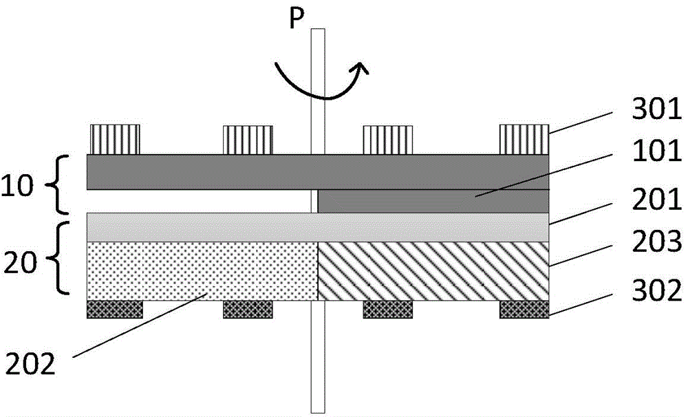
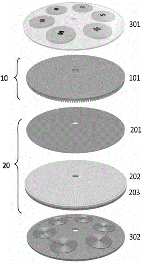
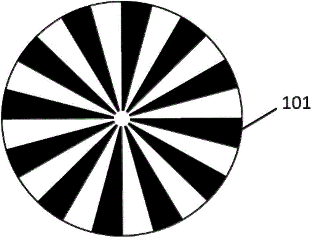
[0043] Secondly, the present invention will be described in detail with reference to schematic diagrams. When describing the embodiments of the present invention in detail, the schematic diagrams are only examples, which should not limit the scope of protection of the present invention.

[0044] For the typical structure of the generator of this embodiment, see figure 1 with figure 2 , Including a friction nano power generation component and a magneto...


PUM

PropertyMeasurementUnit
Number of turnsaaaaaaaaaa
Thicknessaaaaaaaaaa

Abstract

The invention provides a rotary-type compound nanometer power generator. The rotary-type compound nanometer power generator comprises a friction nanometer power generation assembly and a magnetic-electric sensing power generation assembly, wherein the friction nanometer power generation assembly comprises a rotor and a stator which are provided with a command rotation shaft, a friction layer is arranged on the lower surface of the rotor and is formed by outwards and radially arranging a plurality of friction units taking the rotation shaft as a circle center, an electrode layer of the stator comprises a first electrode and a second electrode which are formed by outwards and radially arranging a plurality of first electrode units and a plurality of second electrode units at intervals in the same plane from the rotation shaft, electron gain-loss capability difference exists between the friction units and the upper surface material of the stator, a magnet part and a coil part of the magnetic-electric sensing power generation assembly are separately arranged on the rotor and the stator, and under the effect of an external force, induction potential difference is generated between the two electrodes, and meanwhile, induction current is generated in the coil part. The power generator provided by the invention can acquire current output with milliamperes and can be used for directly supplying power to a small-sized power utilization device.

Description

technical field [0001] The invention relates to the technical field of power generation, in particular to a rotary composite nanometer generator formed by coupling friction effect and magnetoelectric effect. Background technique [0002] With the depletion of traditional fossil fuels (coal, oil and natural gas, etc.) with limited reserves, the energy problem has become a shackle restricting the development of human society. Researchers at home and abroad have turned their attention to renewable new energy sources. Among them, the nanogenerator proposed to solve the energy supply of micro-nano devices and systems has increasingly become the leader leading the development of micro-nano energy. [0003] There have been many reports on nanogenerators based on piezoelectric effect, pyroelectric effect, friction effect, and magnetoelectric effect. Chinese Patent "A Nano Generator System" (CN201320792713), Chinese Patent "Rotary Friction Generator, Voltage Stabilizer Output Circui...

Claims


Application Information

Patent Timeline
IPC IPC(8): H02N1/04H02K21/14
Inventor 杨亚钟贤岱王中林
Owner BEIJING INST OF NANOENERGY & NANOSYST
Why Eureka
Try Eureka