Time-to-contact estimation device and method for estimating time to contact

a technology of which is applied in the field of time-to-contact estimation device and time-to-contact estimation method, can solve the problems of low accuracy, high cost, and limited application, and achieve the effect of low latency and computation

Active Publication Date: 2008-02-21
VEONEER SWEDEN AB +1
View PDF4 Cites 22 Cited by
  • Summary
  • Abstract
  • Description
  • Claims
  • Application Information

AI Technical Summary

Benefits of technology

[0017]An object of the present invention is to provide a method for estimating the time to contact that is based on the time-varying images, or an ...

Problems solved by technology

Such “active” systems can be complex, expensive, subject to interference and limited in spatial resolution, or limited in application because of the need to actively emit radiation and the requirement that the object reflect the radiation.
Binocular stereo systems are expensive, require careful calibration, and make heavy computational demands because of the stereo matching operation (Lucas & Kanade 1981).
However, “feature tracking” methods may be unreliable in estimation of the TTC when errors are contained in the extraction results of the features or feature points and in the calculation therewith in the case in which, for example, the feature points are erroneously correlated with each other, or in the case in which the feature points are erroneously extracted or not extracted and the correlations between the feature points are failed (schematically shown in FIG. 17).
In addition, because the extraction of the feature points requires a significant amount of calculation, it is difficult to realize a high-speed estimation of the TTC.
As a result, the “feature tracking” methods have not been used successfully to estimate the TTC.
Optical flow methods suffer from high computational cost, however, since the optical flow is usually estimated by ...

Method used


Image

  • Time-to-contact estimation device and method for estimating time to contact
  • Time-to-contact estimation device and method for estimating time to contact
  • Time-to-contact estimation device and method for estimating time to contact

Examples


case 1

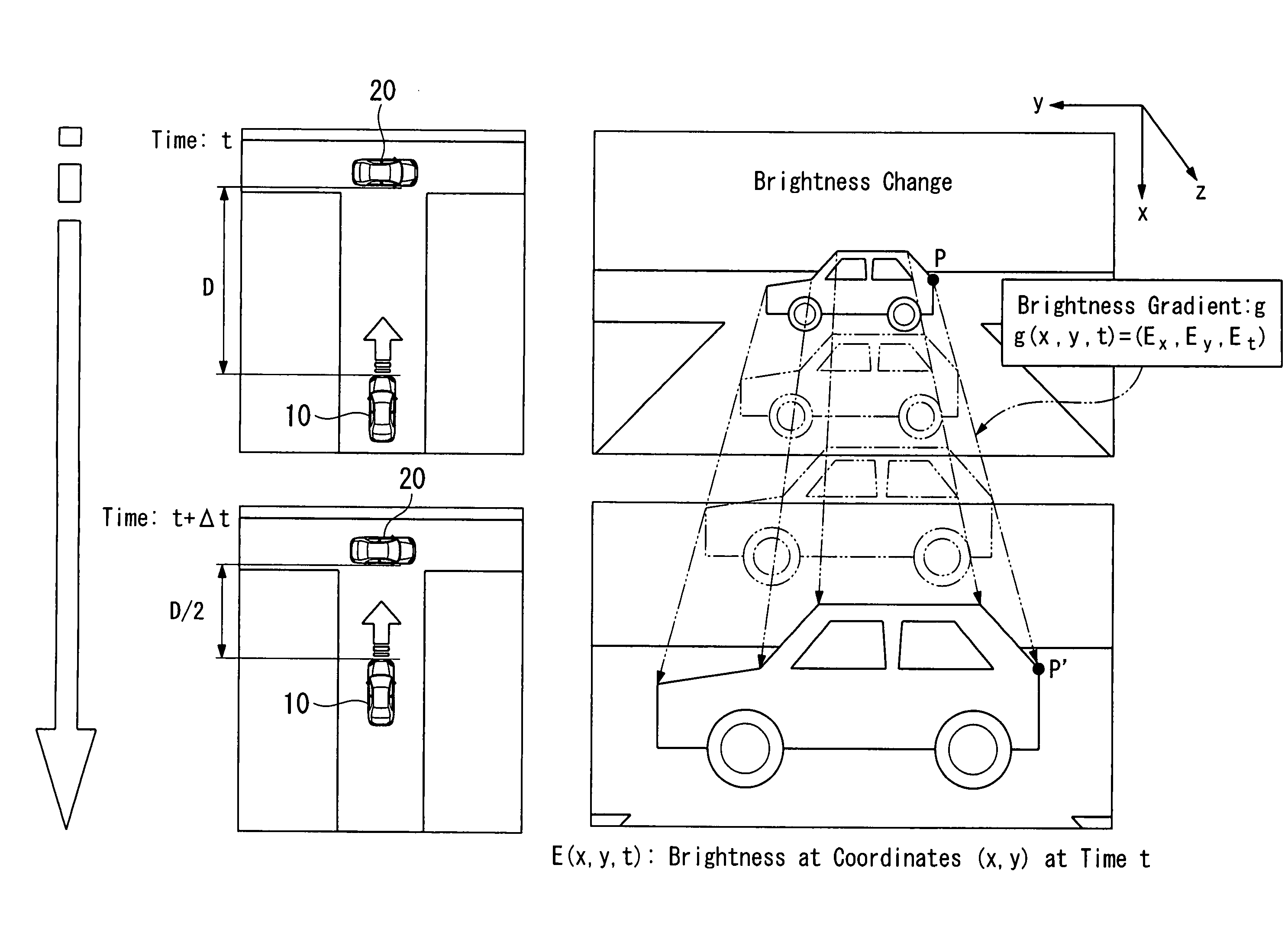
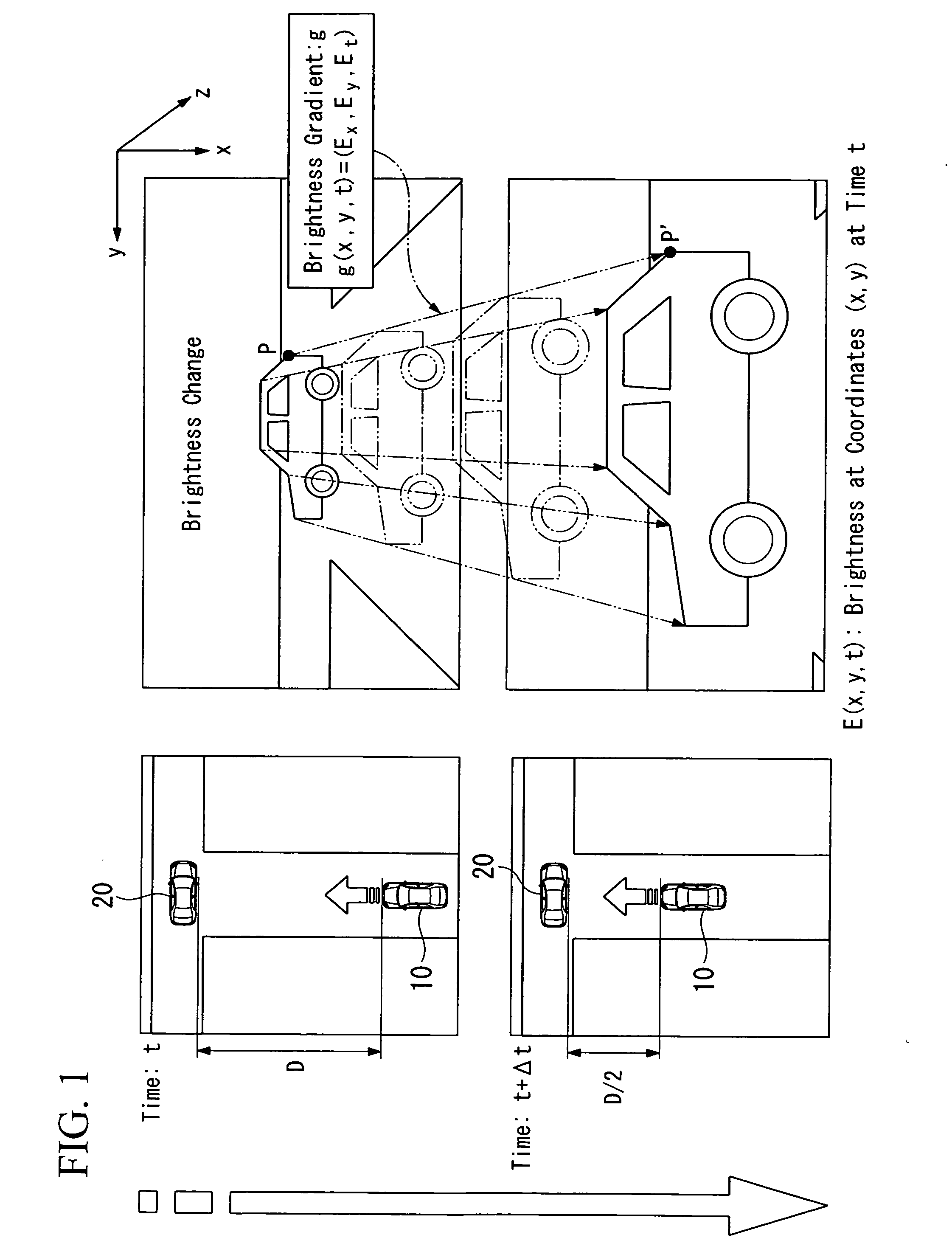
[0071]In Case 1, as shown in FIG. 7, a translational motion of the camera 2 along a translation path 3, which is in parallel with the optical axis 2a of the camera 2 in this case, toward the planar surface 1 fixed perpendicular to the optical axis 2a (i.e., the normal 1a of the planar surface 1 is in parallel with the optical axis 2a and the translation path 3) is discussed. In this case, because the degrees of freedom of the planar surface 1 and the camera 2 are constrained, i.e., the camera 2 moves along the optical axis 2a thereof without rotational motion, the brightness gradient constraint equation is the simplest form. In addition, by assuming that the object to be considered is a planar surface that is oriented perpendicular to the optical axis 2a of the camera 2, motion vector (u,v) in the image (u=dx / dt, v=dy / dy) can be simply expressed as follows,

u=x(W / Z), v=y(W / Z)   C1-(1)

and the time to contact TTC is expressed as follows,

TTC=Z / W   C1-(2)

where W is speed of the camera 2 ...

case 2

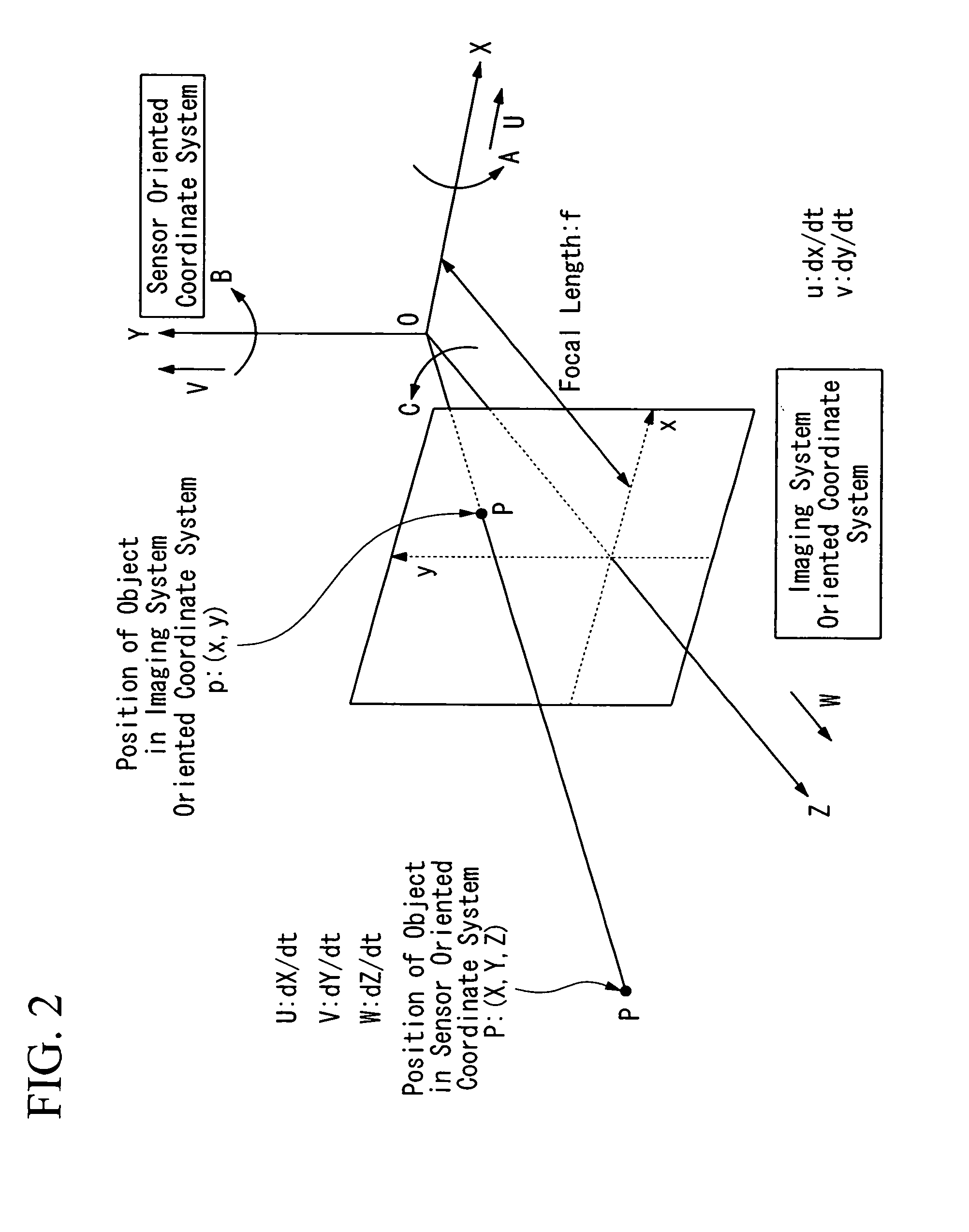
[0086]In Case 2, as shown in FIG. 8, a translational motion of the camera 2 along a translation path 3, which is arbitrarily determined in this case, toward the planar surface 1 fixed perpendicular to the optical axis 2a (i.e., the normal 1a of the planar surface 1 is in parallel with the optical axis 2a) is discussed. In this case, the degree of freedom of the planar surface 1 is constrained, and the degree of freedom of the camera 2 is not constrained, i.e., the camera 2 moves not necessarily along the optical axis 2a, or not necessarily along a line in parallel with the normal 1a of the planar surface 1. U, V, and W shown in FIG. 2 respectively indicate X, Y, and Z component of velocity in the sensor oriented coordinate system. With regard to these terms, following Equation C2-(1) (i.e., brightness gradient constraint equation) is satisfied, where f is focal length of the camera 2.

u=−f·U / Z+x·W / Z, v=−f·V / Z+y·W / Z   C2-(1)

It should be clear that Case 1 discussed above is simply a sp...

case 3

[0101]In Case 3, as shown in FIG. 9, a translational motion of the camera 2 along a translation path 3, which is in parallel with the optical axis 2a of the camera 2 in this case, toward the planar surface 1 of an arbitrary orientation (i.e., the normal 1a of the planar surface 1 is not necessarily in parallel with the optical axis 2a) is discussed. In this case, the degree of freedom of the camera 2 is constrained, and the degree of freedom of the planar surface 1 is not constrained.

[0102]When p and q are defined to be the slopes in the X and Y direction of the planar surface 1 measured in the imaging system coordinate system, the planar surface 1 is expressed by the following Equation C3-(1).

Z=Z0+pX+qY   C3-(1)

X=Z·x / f and Y=Z·y / f are substituting into Equation C3-(1) to obtain following Equation C3-(2).

[0103]

Z(1−p(x / f)−q(y / f))=Z0   C3-(2)

By using the relationship among brightness, these motion vector constraint equations can be expressed by following Equation C3-(3).

[0104]

rEr(1−p·...


PUM


Abstract

A time-to-contact estimation device for estimating a time to contact of a moving body to an object in surroundings of the moving body, includes: an image sensor provided on the moving body, and continuously capturing time-varying images of the surroundings of the moving body; a brightness change calculation unit calculating brightness changes in pixels between the time-varying images captured one after another; and a time-to-contact calculation unit calculating optimized brightness gradients based on the brightness changes calculated by the brightness change calculation unit, and calculating the time to contact of the moving body to the object based on the optimized brightness gradients.

Description

BACKGROUND OF THE INVENTION[0001]1. Field of the Invention[0002]This invention relates to use of an imaging system to determine the time remaining before two objects or surfaces touch. The image sensor may, for example, be mounted on a manually, remotely or automatically operated vehicle of land, sea or air, or on a kinematic chain or robotic arm used in automated assembly or other factory automation.[0003]2. Description of Related Art[0004]Active systems using sonar, lasers, and radar are known in the art for estimating the distance or range to an object or to a point on an object. At times such systems can also be used to estimate velocity by differentiating the range, or by using the Doppler effect. The ratio of distance to velocity could then be used to estimate the time to contact. Such systems actively emit some form of radiation and detect radiation reflected from an object. The distance is estimated from the time delay between emitted and received radiation, the phase shift ...

Claims


Application Information

Patent Timeline
IPC IPC(8): G08G1/16
CPCG06T7/2066G06T2207/10016G06K9/00805G08G1/16G06T2207/30261G08G1/165G08G1/166G06T7/269G06V20/58
Inventor KOIKE, HIROYUKIOGAWA, SHINGOMASAKI, ICHIROHORN, BERTHOLD K.P.FANG, YAJUN
Owner VEONEER SWEDEN AB
Why Eureka
Try Eureka