Latency Reduction In A Low Power Mode

a low power mode and latency reduction technology, applied in the field of telecommunications systems, can solve the problems of significant attenuation of transmitted signals, effectively shutting down the hfc network, and inability to accept voice over cable applications, so as to facilitate communication of control signals and reduce latency in communications systems

Inactive Publication Date: 2011-07-14
AVAGO TECH INT SALES PTE LTD
View PDF23 Cites 235 Cited by
  • Summary
  • Abstract
  • Description
  • Claims
  • Application Information

AI Technical Summary

Benefits of technology

[0011]In one aspect of the present invention a method for reducing latency in a communications system includes monitoring the activity level of a first transceiver, disabling a high power channel as a function of the activity level and activating a low power channel to facilitate communication of control signals from a second transceiver.
[0012]In another aspect of the present invention a method for mitigating latency in a communications system while the communications system is operating at reduced power includes disabling one or more primary communication channels of a first transceiver, disabling one or more connected peripheral devices while the primary communications channel is disabled, receiving messages from a second transceiver, transmitted on a secondary communication channel, wherein the messages are used to restore normal operating conditions when an unscheduled, high priority activity arrives; and wherein the bandwidth of each secondary channel is less than the bandwidth of each primary channel.
[0013]In another aspect of the present invention a two communication system having a power management system that reduces the power of bi-directional communications equipment without introducing significant latency includes a local host having a primary broadband communication channel and a secondary narrowband transmitter and customer premise equipment having a primary communication channel for communicating with the primary communication channel of the local host and a secondary low power out of band receiver that receives out of band control signals from the out of band transmitter during low power operation of the customer premise equipment.
[0014]In a further aspect of the present a method for mitigating latency in a communications system while the communications system is operating at reduced power includes disabling a high power channel of a first transceiver, activating a low power channel of the first transceiver to enable reception of control signals from a second transceiver and activating the high power channel of the first transceiver upon lapse of a predetermined time.

Problems solved by technology

However, the coaxial cable may significantly attenuate the transmitted signal.
Failure of the primary power source in such a system removes power from these active devices, effectively shutting down the HFC network.
Such a network failure may be unacceptable for voice over cable applications that require strict system availability.
In addition, the government also requires system availability in certain locations even if there is a loss of the primary commercial power source.
However, standby power systems are extremely expensive.
Secondly, because of the circuit complexity, maintenance and replacement costs are high.
Thirdly, also because of the circuit complexity, reliability is not high.
The RF circuitry and digital logic required to support and maintain bi-directional communication between customer premise equipment and the cable headend over a HFC network consumes significant amounts of power.
However, the DOCSIS specification does not provide the ability to interface with equipment having power management systems.
However, in lifeline powering situations, equipment that must remain available during a power outage strain the ability of the HFC plant to supply power to all network components.
Therefore, applications that have strict latency requirements may not be supported by such conventional systems.
An example of an application that is adversely affected by this power management technique is voice telephony.
In addition, DOCSIS specifically prohibits the incorporation of network equipment that is not available at all times to respond to maintenance requests.

Method used


Image

  • Latency Reduction In A Low Power Mode
  • Latency Reduction In A Low Power Mode
  • Latency Reduction In A Low Power Mode

Examples


Embodiment Construction

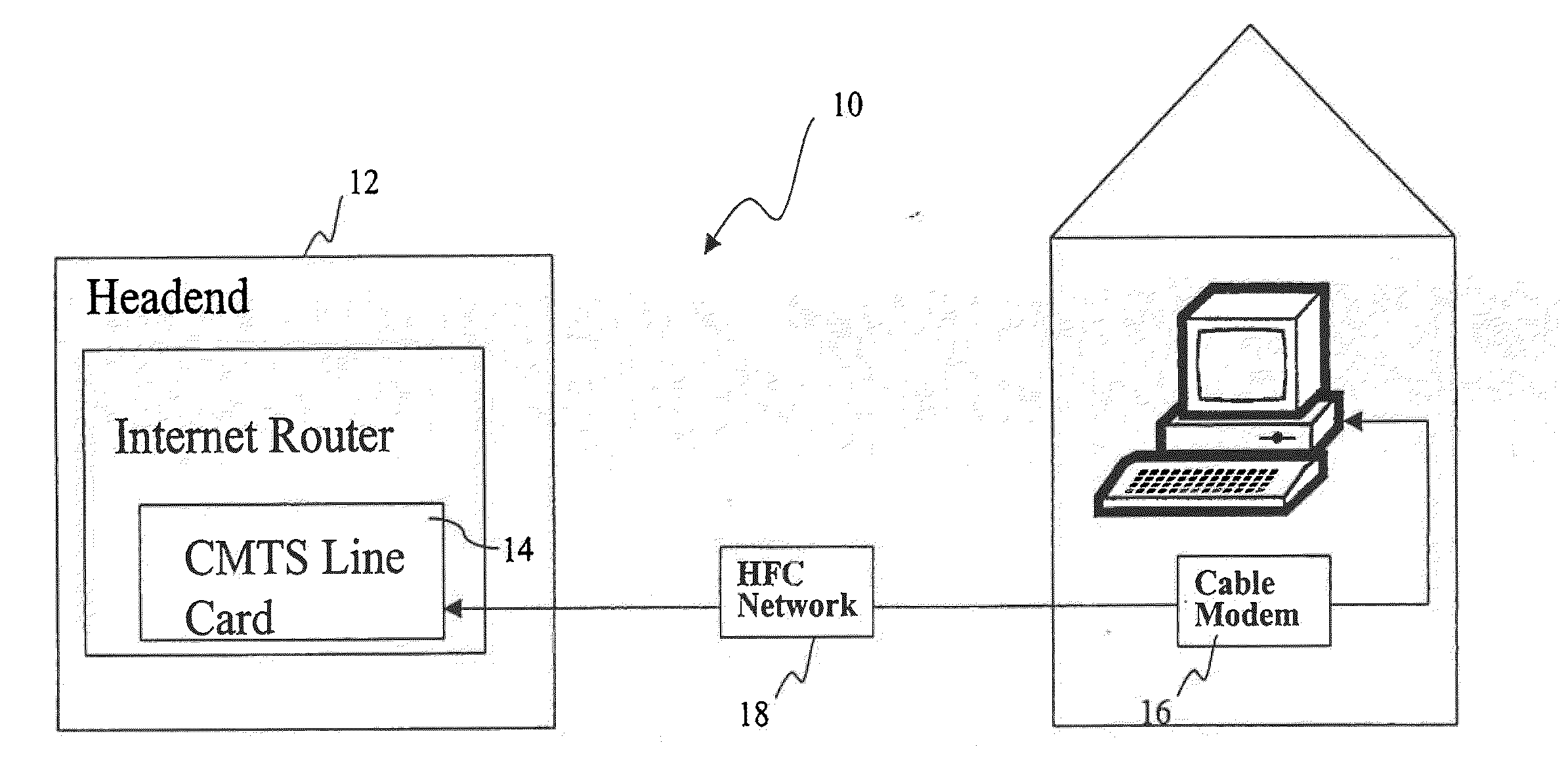
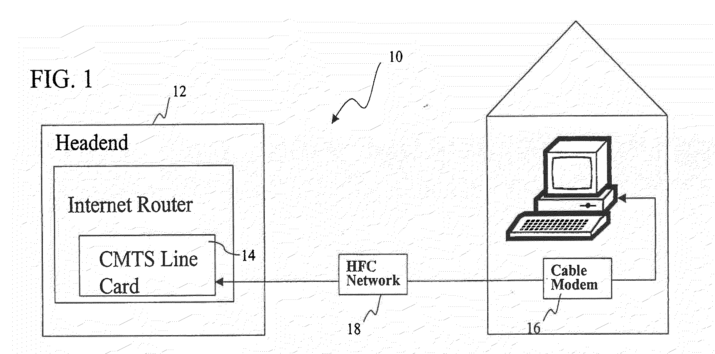
[0029]An exemplary embodiment of the present invention provides a power management system that the power of DOCSIS compliant equipment without introducing significant latency. In order to appreciate the advantages of the present invention, it will be beneficial to describe the invention in the context of an exemplary bi-directional communication network, such as a HFC network.

[0030]A simplified block diagram of a particular exemplary implementation is depicted in FIG. 1. An exemplary cable modem system 10 includes a headend 12 having a cable modem termination system (CMTS) 14 located at a cable company facility. A CMTS utilizing the present invention is disclosed in a U.S. Patent Application entitled “Method and Apparatus for the Reduction of Upstream Request Processing Latency in a Cable Modem Termination System” Ser. No. ______ (Attorney docket B600:36885) filed on even date herewith by Lisa Denney, Angers Hebsgaard, and Robert J. Lee, the disclosure of which is incorporated fully...


PUM


Abstract

A two way communication system is adapted to reduce latency while the communications system is operating in a low power mode. The two way communication system includes a local host having a first primary communication channel and a secondary out of band transmitter; and customer premise equipment having a primary communication channel for communicating with the first primary communication channel of the local host and a secondary low power out of band receiver that receives out of band control signals from the out of band transmitter during low power operation of the customer premise equipment.

Description

CROSS-REFERENCE TO RELATED APPLICATIONS[0001]This application is a continuation of U.S. patent application Ser. No. 10 / 890,177, filed Jul. 14, 2004, which is a continuation of U.S. Pat. No. 6,785,564, filed Aug. 31, 2000, which claims priority to U.S. Provisional Patent Application No. 60 / 151,686, filed Aug. 31, 1999, all of which are hereby incorporated by reference in their entirety.FIELD OF THE INVENTION[0002]The present invention relates generally to telecommunications systems, and more particularly, to a system for reducing latency in low power equipment applications in hybrid fiber coax (HFC) plants.BACKGROUND[0003]The Internet has become a pervasive medium that allows worldwide access to multi-media content including audio, video, graphics and text, that typically requires a large bandwidth for downloading and viewing. Most Internet Service Providers (“ISPs”) allow customers to connect to the Internet via a serial telephone line from a Public Switched Telephone Network (“PSTN...

Claims


Application Information

Patent Timeline
Patent Type & Authority Applications(United States)
IPC IPC(8): H04W52/02H04L12/12H04L12/28H04N7/173H04N7/22
CPCH04L12/12H04L12/2801Y02B60/34H04N7/22H04N7/17309H04N21/6118H04N21/6168Y02D30/50
Inventor QUIGLEY, THOMAS J.RABENKO, TED
Owner AVAGO TECH INT SALES PTE LTD
Why Eureka
Try Eureka