

Sea floor sampling device and method
a sampling device and floor technology, applied in the direction of electric signalling details, instruments, borehole/well accessories, etc., can solve the problems of dangerous and expensive drilling of oil and gas, substantial harm to marine mammals, and high cost of operating such a ship, so as to improve data collection, accurate positioning, and easy operation
- Summary
- Abstract
- Description
- Claims
- Application Information
AI Technical Summary
Benefits of technology
Problems solved by technology
Method used
Image

Examples
Embodiment Construction
[0042]As required, detailed embodiments of the present invention are disclosed herein; however, it is to be understood that the disclosed embodiments are merely exemplary of the invention, which may be embodied in various forms. Therefore, specific structural and functional details disclosed herein are not to be interpreted as limiting, but merely as a basis for the claims and as a representative basis for teaching one skilled in the art to variously employ the present invention in virtually any appropriately detailed structure.
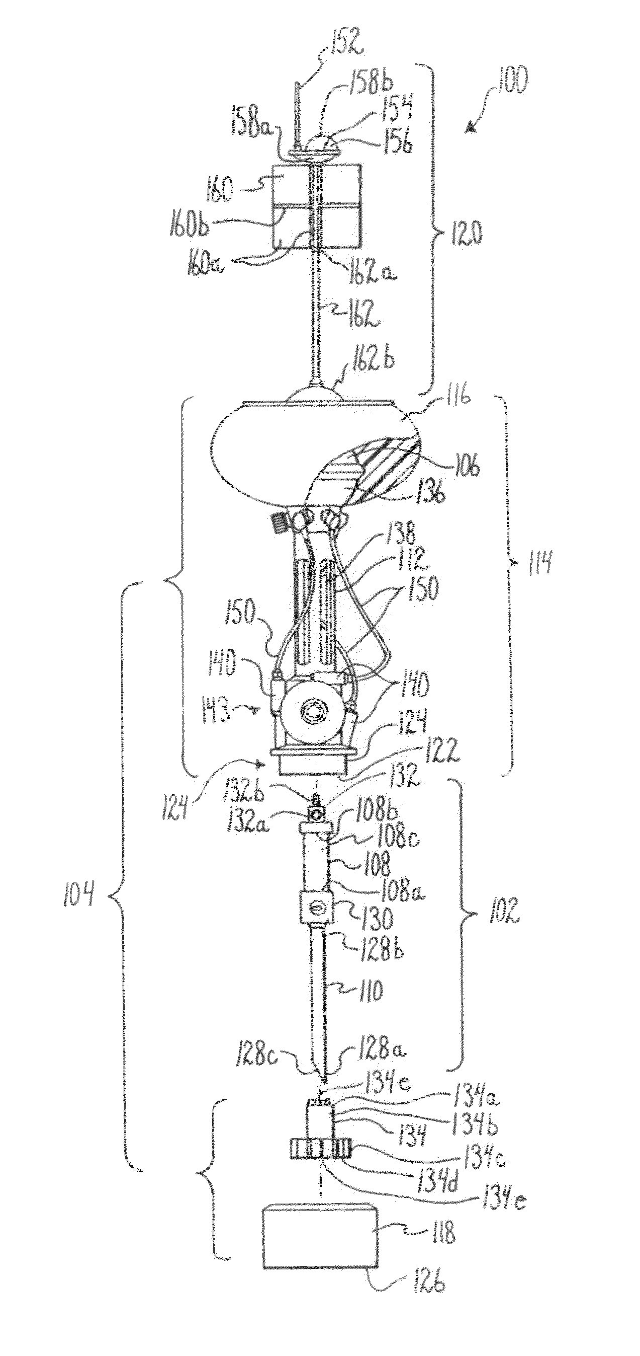
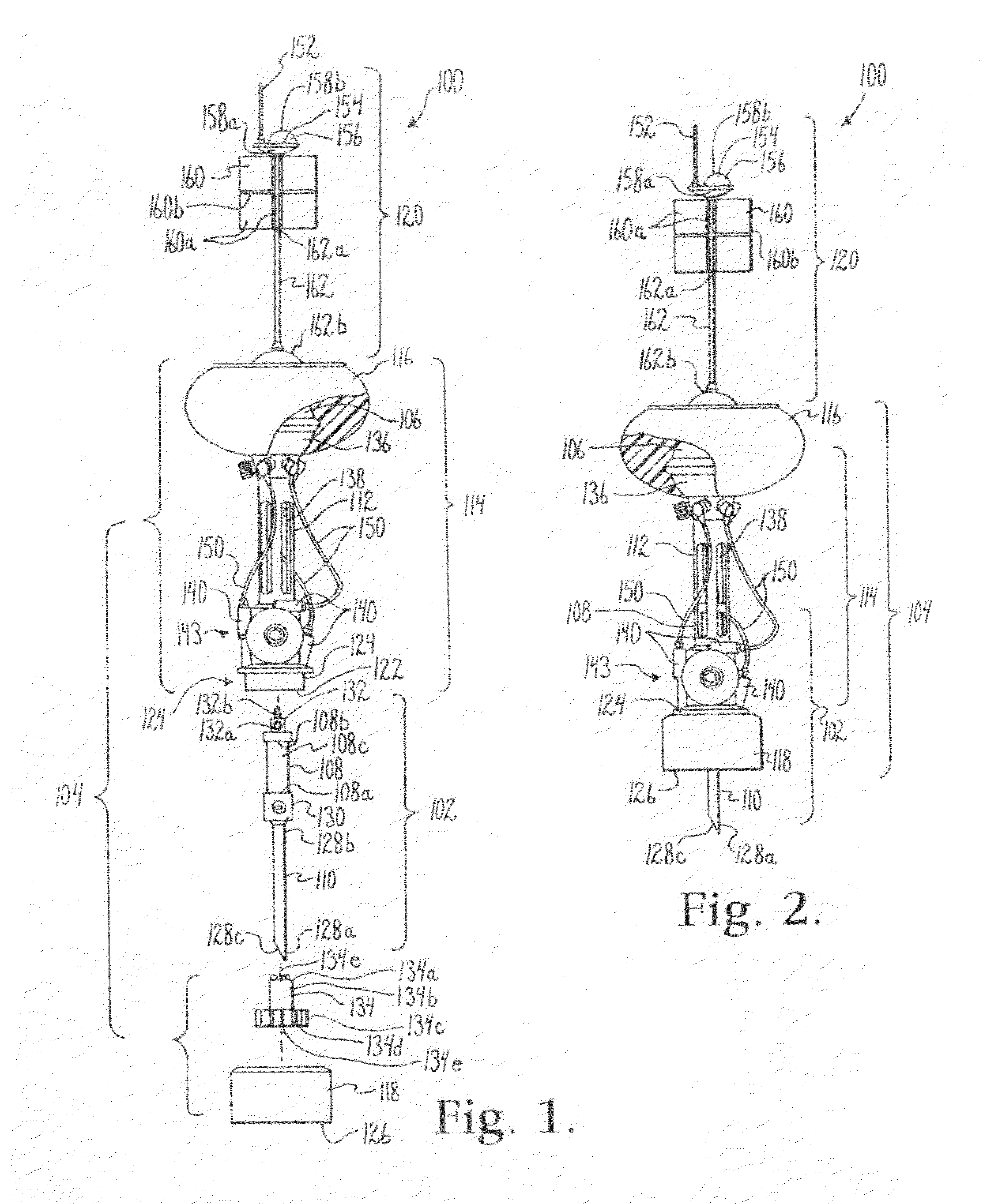
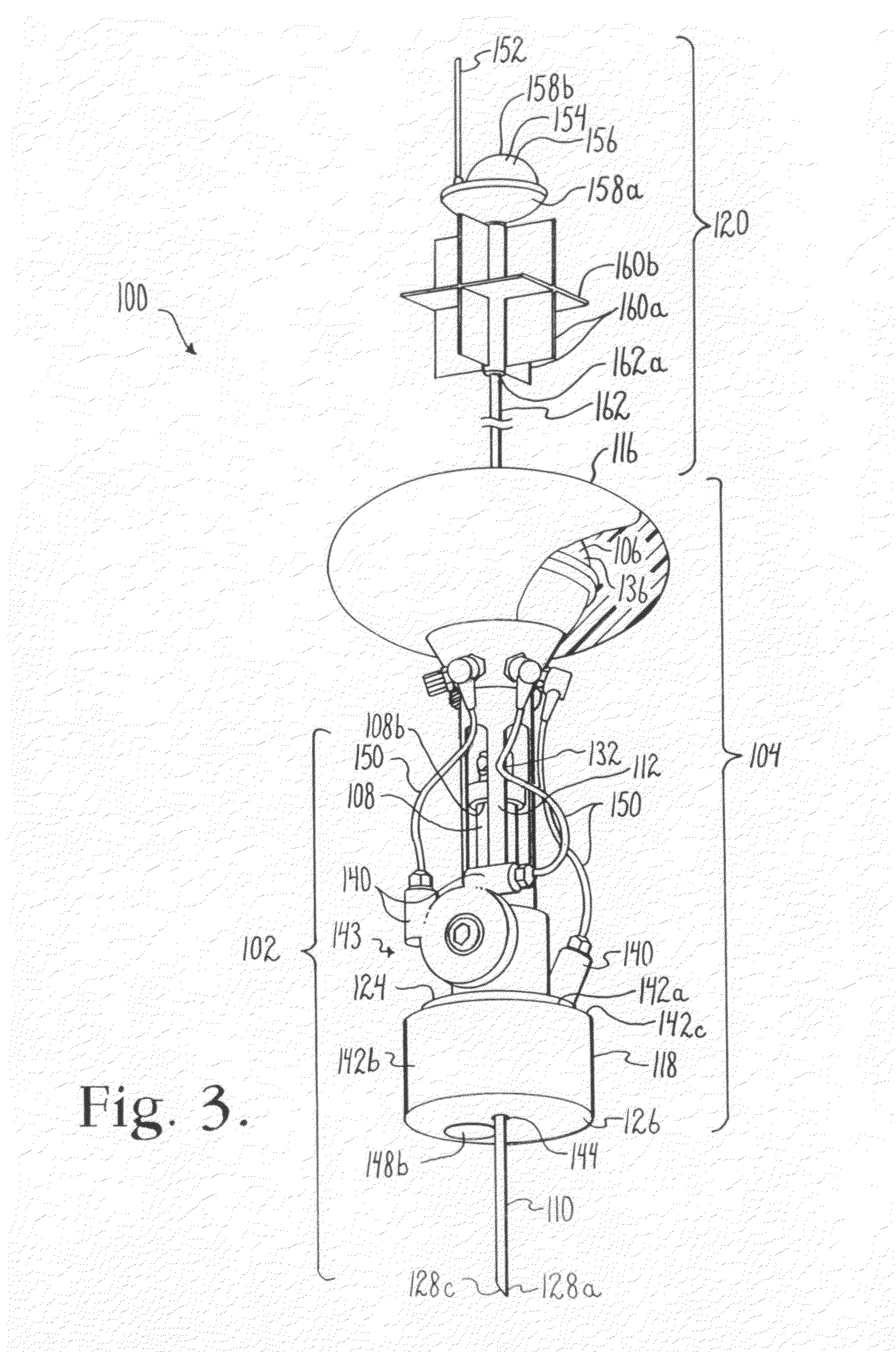
[0043]FIGS. 1-3 illustrate a deep sea floor sampling device generally indicated by the reference numeral 100. The deep sea floor sampling device 100 includes three major components, a sampling apparatus 102, a diving apparatus 104, and a control apparatus 106.
[0044]The sampling apparatus 102 includes a sample ampule 108 with first and second ends 108a, 108b and an interior chamber 108c, and a sampling spike 110 attached thereto. The sampling apparatus 102 is ...
PUM
| Property | Measurement | Unit |
|---|---|---|
| depth | aaaaa | aaaaa |
| depths | aaaaa | aaaaa |
| angles | aaaaa | aaaaa |
Abstract
Description
Claims
Application Information