Oil well liquid-displacement reciprocating oil pumping system

An oil well and liquid flooding technology, applied in the field of liquid flooding rodless pumping system, can solve the problem of inability to adapt to non-oily working medium, etc., and achieve the effects of high power utilization rate, timely commutation response, and uniform working load

Pending Publication Date: 2018-09-07
南京聚源隆能源科技有限公司
View PDF5 Cites 1 Cited by
  • Summary
  • Abstract
  • Description
  • Claims
  • Application Information

AI Technical Summary

Problems solved by technology

It overcomes the disadvantage that the slide valve structure cannot adapt to non-oily working medium, ensures the reliability of the reversing valve, and at the same time places the reversing mechanism in the downhole unit to ensure timely reversing

Method used


Image

  • Oil well liquid-displacement reciprocating oil pumping system
  • Oil well liquid-displacement reciprocating oil pumping system

Examples


Embodiment Construction

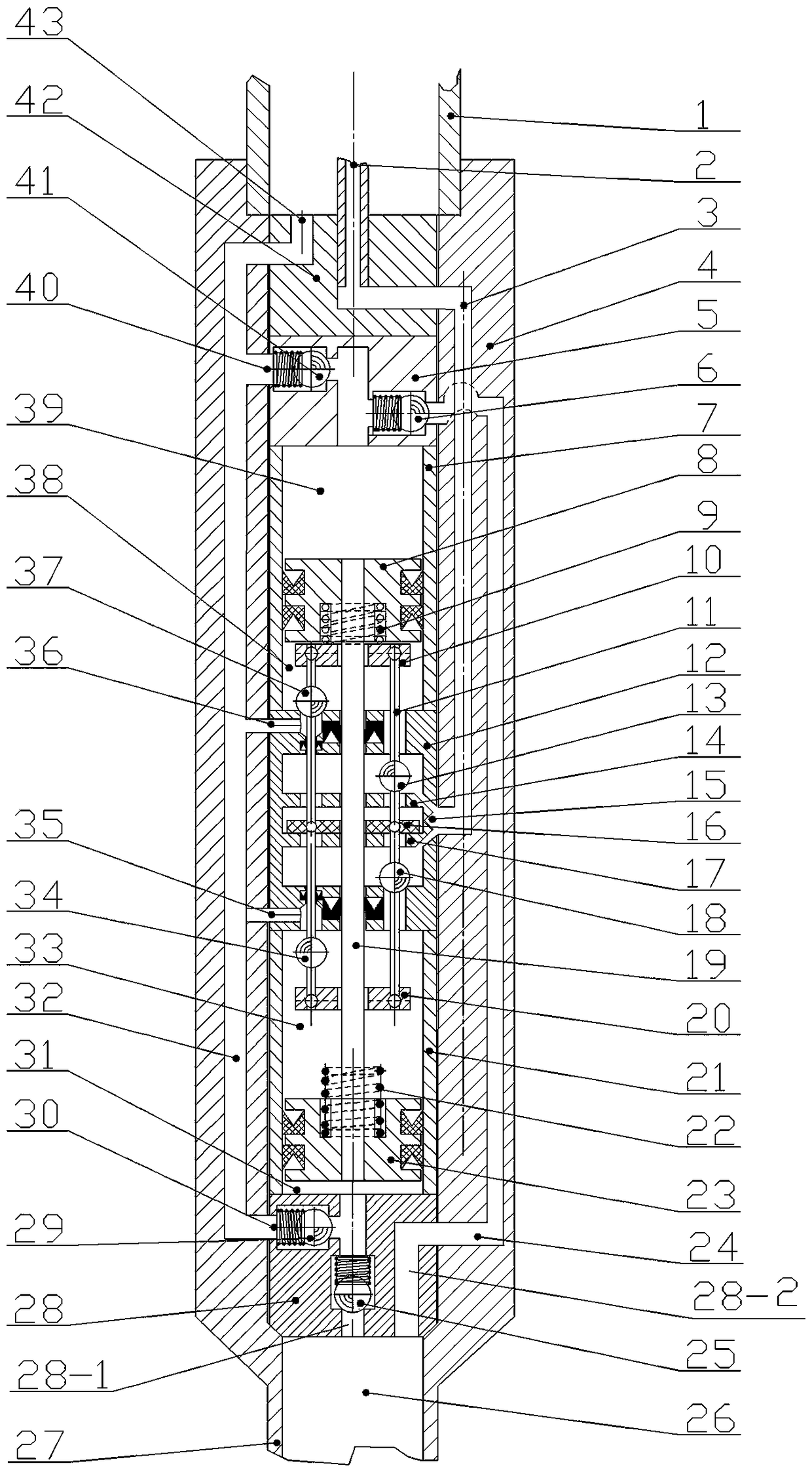
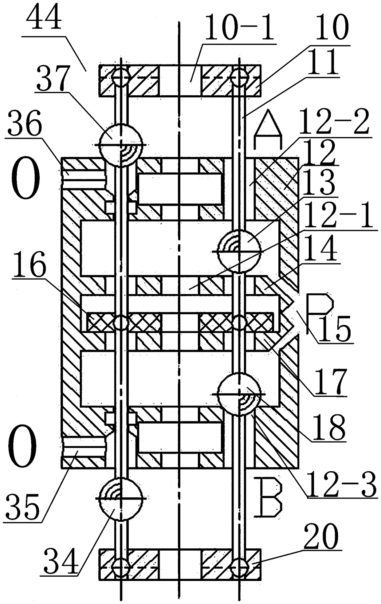
[0027] Reference attached figure 1 , 2 , An oil well fluid flooding reciprocating pumping system includes a working cylinder (4), a hydraulic cylinder A (7), a piston A (8), a produced fluid inlet valve ball A (6), and a produced fluid drain valve ball A (41), piston rod (19), cylinder B (21), piston B (23), produced fluid inlet valve ball B (25), produced fluid drain valve ball B (29), and two-position four Through the reversing valve (44). The working cylinder (4) is connected to the lower end of the tubing (1) and goes down into the oil well along with the tubing (1). The working cylinder (4) is assembled into a whole by the connection of the multi-layer tubing string, and goes down in the oil well with the tubing (1) , The working cylinder is provided with a power fluid channel 3, a formation fluid channel 24, and a produced fluid and depleted power fluid channel 32, which can provide multiple fluid channels such as a power fluid channel, a formation fluid channel, and a pr...


PUM


Abstract

The invention relates to liquid-displacement rodless oil pumping systems in the technical field of artificial lift, in particular to an oil well liquid-displacement reciprocating oil pumping system. According to the oil well liquid-displacement reciprocating oil pumping system, high-pressure power liquid is generated through a ground power device and transferred to a downhole reversing oil pumpingunit through channels such as a power liquid pipe or an oil pipe in a wellbore so as to drive an oil-well pump to work. The oil well liquid-displacement reciprocating oil pumping system comprises a working cylinder, a first hydraulic cylinder, a first piston, a piston rod, a second hydraulic cylinder, a second piston, output liquid inlet valve balls, output liquid drainage valve balls and a two-position four-way reversing valve. The working cylinder is connected to the lower end of the oil pipe and put into an oil well along with the oil pipe. The output liquid inlet valve balls comprise theoutput liquid inlet valve ball A and the output liquid inlet valve ball B. The output liquid drainage valve balls comprise the output liquid drainage valve ball A and the output liquid drainage valveball B. The two-position four-way reversing valve comprises a two-position four-way reversing valve element and a two-position four-way reversing valve seat. The two-position four-way reversing valveelement comprises two sliding rods, a reversing push plate A, a reversing push plate B, a permanent magnet ring, a liquid inlet valve ball A, a liquid inlet valve ball B, a reversing liquid drainage valve ball A and a reversing liquid drainage valve ball B.

Description

Technical field [0001] The present invention relates to an oil well fluid drive reciprocating pumping system, which relates to a fluid drive rodless pumping system in the technical field of artificial lift. In particular, a ground power device is used to generate high-pressure power fluid through a power fluid pipe or tubing in a wellbore. The special channel is passed to the downhole reversing pumping unit to drive the pumping pump. The oil well produced fluid and spent power fluid are transported to the ground through channels such as tubing or oil jacket annulus. Part of the produced fluid is recycled as power fluid after necessary degassing and sand removal. The practical and novel design with high operating efficiency and adaptable to special well types can be widely promoted and applied in the field of artificial lift in oil fields. Background technique [0002] In the field of artificial lift technology in oilfields, the existing artificial lift technology can be divided ...

Claims


Application Information

Patent Timeline
Patent Type & Authority Applications(China)
IPC IPC(8): F04B9/113F04B47/08F04B47/10F04B49/00F04B53/10
CPCF04B9/113F04B47/08F04B47/10F04B49/002F04B53/10F04B53/1002
Inventor 徐晓明刘猛刘强
Owner 南京聚源隆能源科技有限公司
Why Eureka
Try Eureka