Clamping-strap-length adjustable hose clamp
A technology of cuffs and throat cuffs, applied in the field of throat cuffs, can solve problems such as inconvenience and increase in production cost, and achieve the effect of convenient connection and installation
- Summary
- Abstract
- Description
- Claims
- Application Information
AI Technical Summary
Problems solved by technology
Method used
Image

Examples
Embodiment Construction
[0022] The following description serves to disclose the present invention to enable those skilled in the art to carry out the present invention. The preferred embodiments described below are only examples, and those skilled in the art can devise other obvious variations.
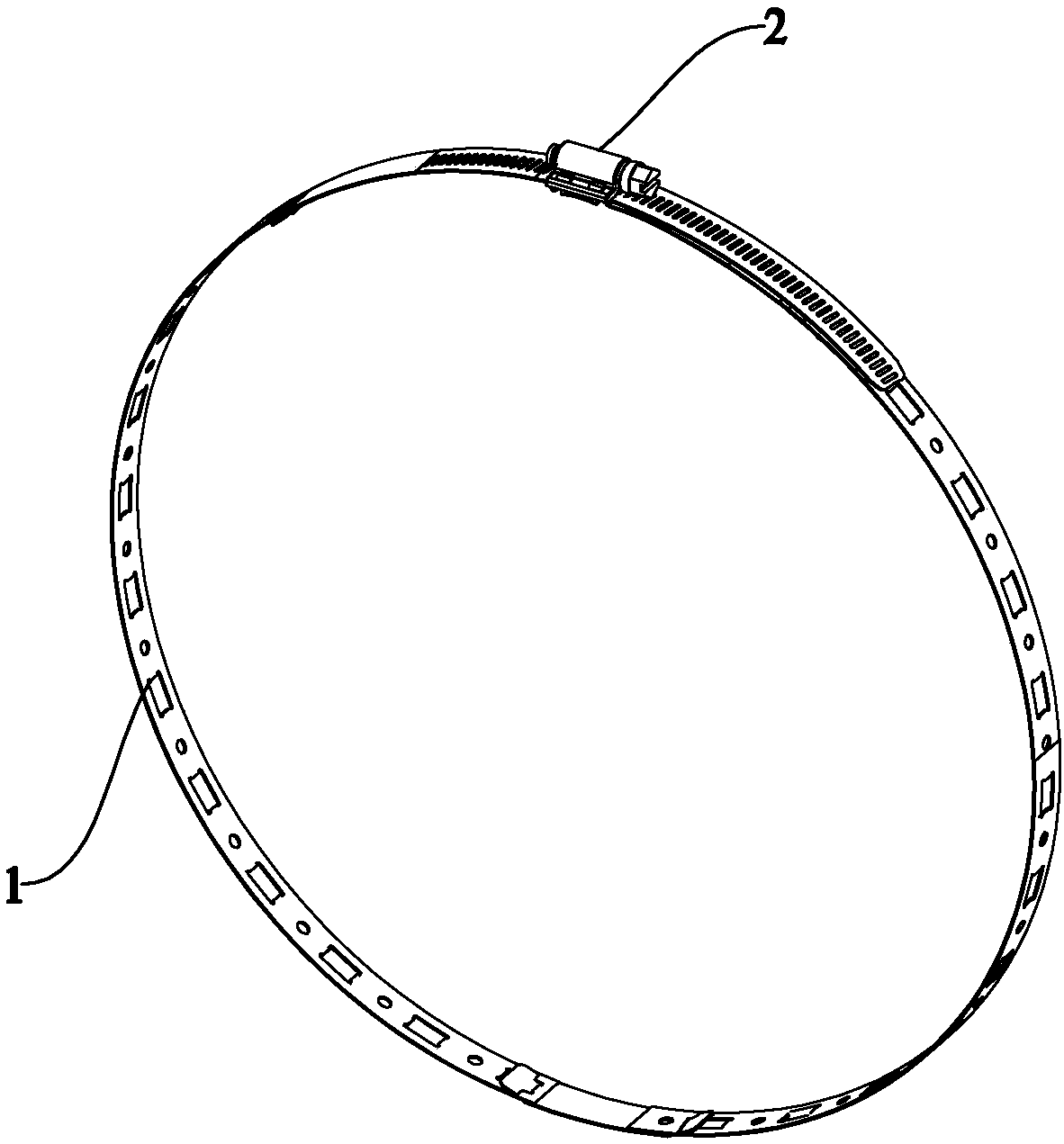
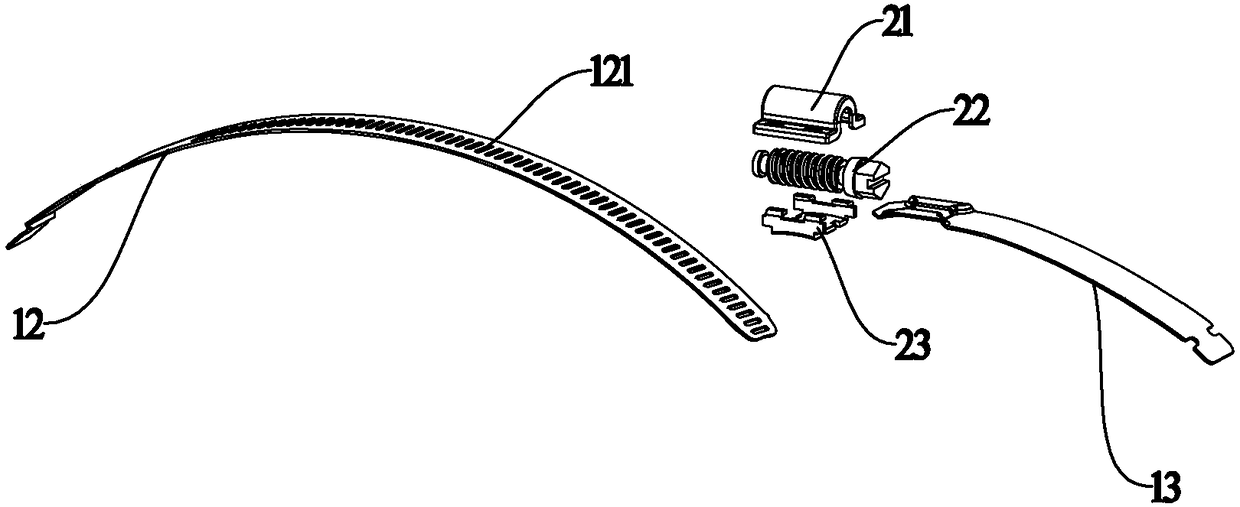
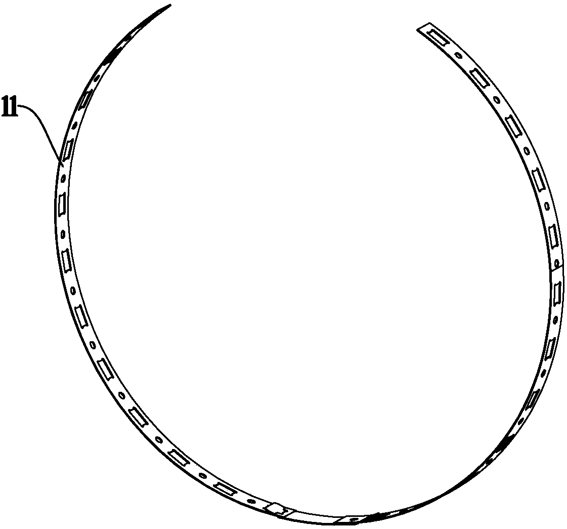
[0023] Such as Figures 1 to 7 A throat clamp with adjustable band length is shown, which includes a band 1 and a worm adjustment part 2. The band 1 includes a first connecting section 12, a band body 11 and a second connecting section 13. The band On the belt body 11, connecting holes 115 are arranged at equal intervals along the extending direction of the band 1. The worm adjustment part 2 is composed of a base 23, a worm 22 and an upper cover 21. The worm 22 is arranged on the base 23. The upper cover 21 covers the worm 22 and is fixedly connected with the base 23. One end of the second connecting section 13 is provided with a fixing part 131, and the fixing part 131 is fixedly connected with the worm ad...
PUM
 Abstract
Description
Claims
Application Information